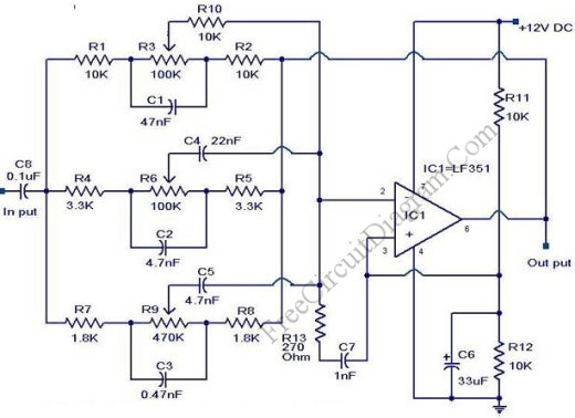
Active Crossover Circuit: Split The Audio Signal Before Amplification

You might be familiar with passive crossover network installed inside your speaker box, consist of inductors and capacitors. The problem with passive crossover network is that they dissipate the audio power, so it’s not environmentally friendly, contributing a little disaster of global warming.  Moreover, the capacitor and the inductor in the passive crossover network contribute the distortion of the signal […]

Read more

Infrasonic and Ultrasonic Filter for High Fidelity (Hi-Fi) Audio System

In high fidelity (hi-fi) audio system, the harmonic distortion level is kept as low as possible. To make sure that the amplifier handle the sigal perfectly, the response of many hi-fi audio systems is designed beyond the audio range, include the handling capability to process infrasonic (below 20Hz) and ultrasonic (higher than 20kHz) signals. Although this capability is useful to […]

Read more

Two Stage Phono Pre-Amplifier with Very Accurate RIAA Response Curve

To produce a pre-amplifier with accurate RIAA response, this circuit use two stages of amplifier. This circuit is more complex than single op-amp RIAA pre-amp, but the performance is excellent in terms of accurate frequency response. Here is the schematic diagram of the circuit. The circuit uses LM833 high performance op-amp from National Semiconductor, giving the best performace of 0.1 […]

Read more

Gramophone Pre-Amp: A Pre-Amplifier with RIAA Response Curve

Recording Industry Association of Ameria (RIAA) has developed the recording standard of response curve for their recording. This curve is developed to optimize the gramophone recording response for lowest signal-to-noise ratio for gramophone technology. Because the tape recording response is not linear, the pre-amp for gramophone playback pickup should have such  response that restore the original response, a flat response […]

Read more

Notch Filter: The Circuit’s Diagram and The Design Formula

Notch filter is known as band-cut filter or band-reject filter. The fuction of this filter is to remove some frequency portion of a signal. The schematic diagram of this filter circuit, a second order notch filter is depicted in the figure below. The formula is actually complicated, but by taking the R3=R4 and C1=C2, the filter’s frequency response  formula become […]

Read more

Transistor Hum Notch Filter

The function of this circuit is similar with the hum filter in our previous circuit, but it use transistors instead of op-amps. It uses BC109 transistors, but any low noise high gain type will be suitable. This hum filter is adjustable via trimmer pots to fine tune it’s notch depth.   The figure below shows the schematic diagram of the […]

Read more

3-Band Graphic Equalizer Circuit

Unlike the 10-band graphic equalizer in our previous circuit that use a gyrator circuit, this 3-band graphic equalizer circuit uses Baxandall topology, similar with the Baxandall tone control but with additional mid frequency control. The figure below shows the schematic diagram of the circuit. The operational amplifier employ an LF351 IC chip, but any low noise op-amp will be suitable […]

Read more
1 2 3