Overload Protector for Batteries and Power Supplies
This circuit is used to prevent the damaging effects of a reversed-polarity battery or short-circuit load. It is used to replace the simple fuse that usually used for overcurrent protection because the fuse has long reaction time and high resistance. This circuit consist of dual comparator, a combination of current amplifier, and external CMOS. A logic-controlled switch can provide low quiescent current and low-loss switching in addition to output short circuit protection. Here is the logic-controlled switch circuit:
This circuit will turn on when we applying VBATT to the on/off input. Gate drive of VBATT + 10V for the nMOSFET switch, Q1 generated by The MAX623 regulated charge pump (IC1). The MAX9943 op amp (IC2) receive power from the Vout. Short-circuit protection is provided by feedback through R1. The gate drive goes low and turns off Q1, if high load current pulls the source voltage below the reference level at the inverting input.
Figure below shows the circuit that blocks the effect of a reversed-polarity battery. In this circuit there are two mosfet, one is pMosfet (Q1) that provides passive protection against battery and another is MOSFET (Q3). Q3 turns off and disconnects the battery from the load, when the load current causes sufficient voltage across R8 to trip the B comparator.
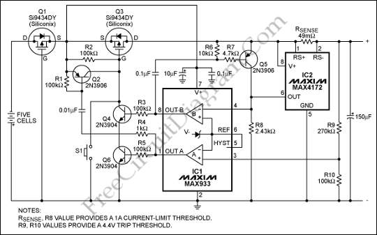
As a safety valve this circuit uses comparator A that turns off Q3 in the event of a rapid short circuit. Here is the current limit equation : ILIMIT = VTH/R8 × 100/RSENSE