Error Compensation Circuit for Pressure Sensor

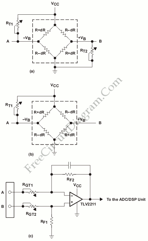
To obtain an accurate pressure value, we must remove the offset errors. There are many basic circuit designs that is used to remove the offset errors. This circuit uses three method to remove the offsets errors, they are symmetrical offset trim, asymmetrical offset trim and amplifier gain adjustment. Here is the circuit:

The differential sensor output must be zero V when the lowest expected pressure is applied. That will happen if only one operational amplifier is used in the amplifier stage. First solution to remove the offsets errors is symmetrical offset trim. It is shown by figure (a), the output signal on each side can be moved to VCC/2 for the lowest pressure point by the RT1 and RT2. It will reduce the sensor’s sensivity but only a relatively small amount (1.66%) because this application uses resistor with values about 100k range. However this solution has disadvantage, this solution need two trim potentiometers.
To reduce the trim potentiometers in first solution, we can use second solution (figure (b)).This solution uses only RT1 and trims the output on only one side to the same voltage level as the other side. It also reduces the sensitivity of the sensor approximately 2%, but it can be saved by one step of calibration. For the pressure sensor that has variation of sensitivity, We can use variable amplifier gain to remove the offsets errors (figure (c)). But it need 2 potentiometers to trim the gain. It will cause the cost rise. [Source: Texas Instruments Application Report]