Capacitor ESR Meter
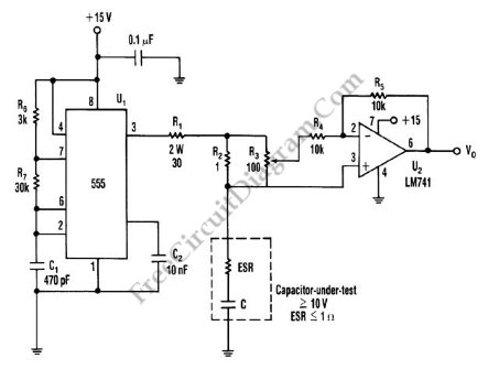
This is schematic diagram of capacitor ESR meter circuit. ESR is equivalent series resistance, and this parameter is used to express the resistance value of any electronic component that basically is not a resistor. ESR is present on many non-resistor component, such as capacitor, inductor, or semiconductor. The circuit shown in this schematic diagram is used to measure equivalent series resistance (ESR) of a capacitor. This ESR meter circuit uses 555 IC as 50-kHz square-wave generator. The ±180mA current waveform is driven in the capacitor-under-test by U1, through R2 and R1. Adjust R3 to the proper value, the inverting amplifier (U2) will null the voltage drop across the equivalent series resistor. The minimum voltage that can be produced at VO the pure capacitor voltage. Here is the schematic diagram of the circuit:
To measure capacitor’s ESR, adjust R3 until VO is minimized and then note the position of the potentiometer and multiply it by the value of R2. Since the capacitor is biased at about 7.5 V, this circuit does not work on Lower-voltage capacitors. The range of ESR that can be measured is determined by the value of R2. The buffer is needed, when the smaller R2 is used because to keep a reasonable voltage across R2. Using the values shown on the circuit, the capacitor that can be measured is greater than 100uF. The smaller values will cause the ripple voltage and decrease the accuracy. [Circuit’s schematic diagram source: seekic.com]