Photocells (Photoconductive, Photodiode, and Photovoltaic) Amplifiers

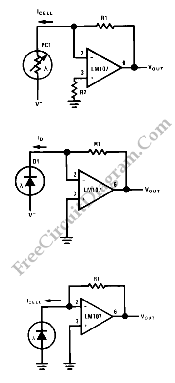
The figures below show us about amplifiers for photoconductive (top), photodiode (mid) and photovoltaic cells (bottom).

Some voltage dependence of both speed and linearity is displayed by all photogenerators. If the cell terminal voltage is allowed to vary with cell conductance, the current through a photoconductive cell will not display strict proportionality to incident light. Functions of terminal voltages are photovoltaic cell internal losses and photodiode leakage. By fixing a constant terminal voltage, zero in the case of photovoltaic cells and a fixed bias voltage in the case of photoconductors or photodiodes, the current-to-voltage converter neatly sidesteps gross linearity problem. By operating into a fixed low load impedance, photodetector speed is optimized. Currently available photovoltaic detectors display response times in the microsecond range at photoconductors and zero load impedance, even though slow, are materially faster at low load resistances. R1 is feedback resistance. R1 is dependent on cell sensitivity and have to be chosen for either a desired scale factor or for maximum dynamic range. R2 in the case of photovoltaic cells or of photodiodes is elective. R2 is not required in the case of photoconductive cells. To minimize bias current error over the operating range, R2 should be chosen. [Source: National Semiconductor Application Note]