Simple pH Meter

pH Meter Circuit
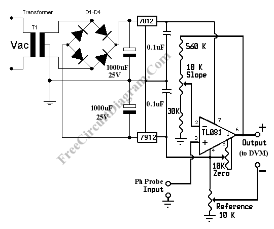
pH meter measures the voltage (the EMF, electromotive force) generated by the pH electrodes (the sensor) to show the hydrogen concentration in pH scale. Basically, a pH meter is nothing more than a pH probe/sensor with high impedance voltmeter that measures the generated voltage at the pH probe. To measure the pH with a standard digital voltmeter (DVM), all you need is just a pre-amplifier that provide the high impedance interface with the gain that match the pH-Voltage conversion factor. Here is one example of pH meter circuit diagram:

pH Meter Calibration
Before the pH meter can be used, it should be calibrated first. Here is the steps to calibrate this pH meter circuit:
- Null the amplifier by shorting the pH probe input to ground. Measure the voltage between output + and ground. Adjust the zero potentiometer until the voltmeter reading show zero volt (or close to zero).
- Now connect pH probe input to a 413 mV voltage source. You can use a potentiometer to make a simple 413 mV voltage source. After connecting the input to 413 mV source, then measure the + output and ground using the digital voltmeter and you should read 7.00 volt. If not then adjust the slope potentiometer until you get the closest reading to 7.00 volts.
- Short the pH probe input to ground. Connect the digital voltmeter voltmeter between – output and + output. Now adjust reference potentiometer until the voltmeter show 7.00 volts. This corresponds to the neutral pH of 7.
- Connect the pH probe input to a pH electrodes (pH probe/sensor), now the pH meter is ready to use. The voltmeter reading in volts would be direct conversion of pH. pH value of 7 would be read as 7 volts, pH 3 as 3 volts, etc.
[Source: simplecircuitdiagram.com]