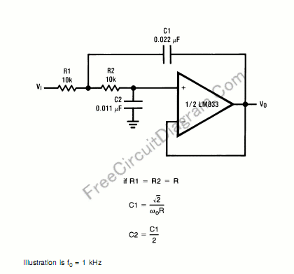
Second Order Butterworth Low-Pass Filter

A second order filters can be constructed using LC (inductor-capacitor) passive circuits, and they have been implemented for radio frequency for cheap and simplicity. For audio frequency range, unfortunately the size for the inductor and capacitor become too large, space consuming, and the most important is they’re really expensive. Because of this, active filter is commonly used for audio application. Here is the circuit’s schematic diagram:
You can use the formula to modify the component values to suit your need. Please keep in mind that the resistor value should be:
- Much higher than the operational-amplifier’s (op-amp’s) input impedance.
- Much higher than equivalent leakage resistance of the capacitor.
- Doesn’t draw excessive current-violating the maximum allowed op-amp’s output current.
Generally, for higher capacitor value, it’s leakage current would be higher and you must use lower resistors to get the formula works as expected. [Circuit’s schematic source: National Semiconductor’s LM833 Application Notes]