Wheatston Bridge PWM Signal Conditioner

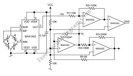
This is a schematic diagram of a Wheatston Bridge PWM Signal Conditioner circuit. This circuit uses the MAX1452 signal conditioner. A ratiometric compensated output for the Wheatstone Bridge is generated by the MAX1452. Then the output of the Wheatston bridge is converted to a PWM output. the PWM-output duty cycle changes accordingly, as the MAX1452 output changes with pressure. the analog-output signal-conditioning ASICs can be used to substitute the MAX1452. Here is the schematic diagram of the circuit:

Frequency counter with pulse-width-measurement option is the instrument that use the circuit. It need an accurate measurement of the PWM output’s pulse width. Beside that, a microcontroller can use the PWM output and the controller’s internal timer to calculate the time interval between high-to-low and low-to-high transitions. To calculate coefficients required to program the signal-conditioning IC, the measured PWM value can be used. [Circuit’s schematic diagram source: maxim-ic.com]