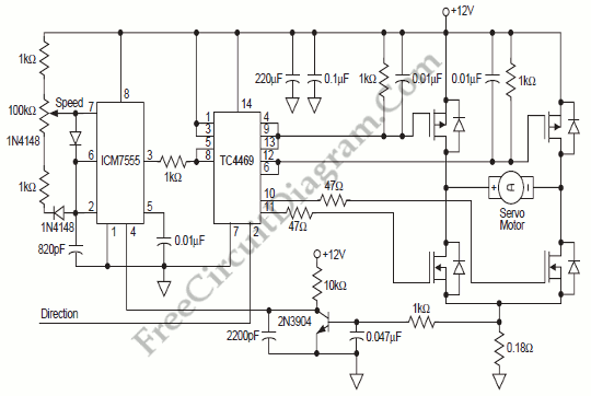
555 IC PWM Motor Control with Current Limiter

To provide rapid motor speed changes and motor direction reversal, four outputs drive a MOSFET H-bridge. N-channel devices are the lower rail power MOSFETs and P-channels are the upper MOSFETs. All of them are driven by the TC4469.

A small series resistor helps prevent gate oscillation and slows transition time in the lower rail devices, helping the upper device to stay OFF. A resistor divider and low-cost level shift transistor can be added easily and economically to maintain a 15VDC gate drive for the upper rail MOSFETs for motor voltages over 12VDC.
A simple linear regulator can power them from the positive motor supply when it is above 15VDC since the ICM7555 and TC4469 need negligible current. To help protect the gates from supply transients, we can use a Zener diodes. When the lower MOSFET in the same leg turns “ON”, causing a high dV/dT, gate-to-source capacitors help keep the upper MOSFETs “OFF”. The other way to help that situation is keeping the upper MOSFET gate drive impedance low in the “OFF” state.
An easy way to sense motor current, pulse by pulse, regardless of forward or reverse motor rotation is provided by a sense resistor in the ground leg of the H-bridge. To inhibit PWM generation if motor current exceeds the allowed value, this signal is filtered and applied to the ICM7555. [Microchip Application Notes]