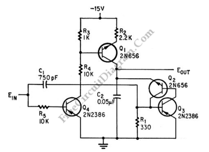
Pulse Width to Analog Voltage Demodulator

This is a schematic diagram of a pulse width to analog demodulator circuit. This circuit is used to demodulate the pulse width to analog voltage level. With input pulse width range of 0 to 1 microsecond, this circuit can produces Output range of 0 to 10 v. The input pulse is integrated and the final value is held until next pulse arrives. Then for next integration, the output return to zero. Here is the schematic diagram of the circuit:

[Circuit’s schematic diagram source: seekic.com]