Simple Stand-Alone Voltage-to-Frequency Converter Using LM231/LM331
Using LM231/331 chip, we can build a low-cost voltage-to-frequency converter, ideal for analog-to-digital conversion, frequency-to-voltage conversion, long-term integration, linear frequency modulation-demodulation, and many other functions. When it’s used as voltage-to-frequency converter, the output will be a pulse train with frequency linearly equal to the applied input voltage. For higher level of accuracy against temperature drift, LM231A/LM331A can be used, let’s design simple and low cost solution but with high performance like as we find in expensive voltage-to-frequency modules. Other application can be a low cost analog-to-digital conversion for microprocessor/microcontroller system, as simple as counting it’s output pulse in a predetermined time period, easily done with many microcontroller series.
Here are some of LM231/331 main features:
- Low cost
- Split or single supply operation
- Guaranteed linearity 0.01% max
- Operates on single 5V supply
- Improved performance in existing voltage-to-frequency conversion applications
- Pulse output compatible with all logic forms
- Wide range of full scale frequency: 1 Hz to 100 kHz
- Excellent temperature stability: ±50 ppm/?C max
- Low power consumption: 15 mW typical at 5V
- Wide dynamic range, 100 dB min at 10 kHz full scale frequency
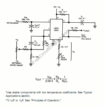
A simple stand-alone voltage-to-frequency converter shown in the schematic diagram below show the basic circuitry with few components to improve its performance.
In the input path, a resistor RIN=100k (10% tolerance) has been added, and cause the bias current at pin 7 (-80nA typical) will cancel the bias current effect at pin 6 to help providing minimum frequency offset. The resistor RS at pin 2 can be implemented using 12k fixed resistor plus 5k variable resistor (trimmer potentiometer), providing adjustment to trim out the gain tolerance of LM231/331, Rt, RL, and Ct.
For the best result, it’s recommended to use low temperature-drift resistors, such as metal-film resistors. Capacitor with low-dielectric absorption is the best, and depending on the desired temperature characteristic, NPO ceramic, polystyrene, teflon, or polypropylene would be suitable.
A voltage step at VIN will cause a step change in fOUT when the RC time constants are matched at pin 6 and pin 7, If CIN is much less than CL, a step at VIN may cause fOUT to momentarily stop. To help the input comparator provide the excellent linearity, a hysteresis should be provided, and it’s done by the component A47R resistor, in series with the 1 µF CL.
Using the components values as shown in the figure, this voltage-to-frequency converter circuit gives 10Hz -11KHz variation for 0-10V input voltage variation, with only 0.03% maximum nonlinearity. [Circuit’s schematic diagram source: National Semiconductor Application Notes]