Amplitude Average Detector

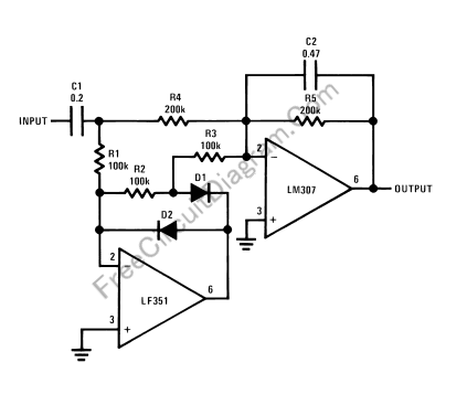
This circuit is similar to peak detector, but the the output won’t immediatelly follow the input peaking. Because the output follow the input peak slowly, averaging effect will be seen at the output. In the figure below you can see the circuit’s schematic diagram.
Use 1% resistor for R1, R2, R3, and R4, and you can achieve negative and positive cycle difference of 0.5dB at the worst case. If you use 5% resistors then the difference between positive and negative cycle gain difference would be about 2dB (worst case). The averaging time constant will depend on R5-C2, you can change to other values if needed. [Circuit’s schematic diagram source: National Semiconductor Application Notes]