Precision Full-Wave Peak Detector: Detect The Envelope of An Audio Signal

This circuit detect the amplitude of audio signal, suitable for audio level detection that demand for high precision. Amplitude detection or signal envelope detection is usually implemented using a peak detector. An ideal amplitude detector give continuous level at any time because the amplitude of a sine signal (every signal can be seen as sine signal combination) is exist and […]

Read more
Precision Half-Wave Peak Detector

A simple half-wave peak detector using a single transistor is very compact and low cost, but if the application require precise detection for signal under 100mV then that circuit become useless. Here you can use more precise half-wave peak detector circuit using only a single op-amp with few passive components. Look at the circuit’s schematic diagram of the peak detector […]

Read more

Single Transistor Half-Wave Peak Detector Circuit

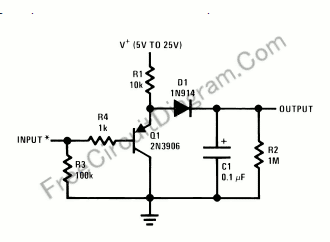
Using only a single transistor and few passive components, you can build a fairly sensitive peak detector. circuit This peak detector circuit is suitable for audio application, since the average sum of positive and negative cycle of audio signal has equal value. You can find a peak signal although you only detect the peak of positive cycle. Here is the […]

Read more

Automatic 12V Lead-Acid Battery Charger

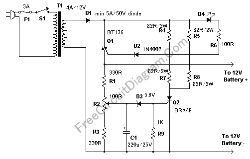
This charger circuit is suitable for lead-acid battery, including flooded, gel, and AGM types. The automatic term means that this charger will stop charging automatically when the battery voltage reach a certain pint, indicating that the battery has been fully charged, and charging will be restarted if the battery voltage falls below that threshold. A LED indicator is provided to […]

Read more

Audio Frequency Meter Using 555 IC

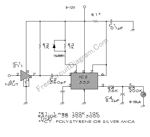
This audio frequency meter uses 555 IC as a monostable multivibrator (one-shoot trigger). A monostable multivibrator can act as a frequency-to-voltage converter because it produce a fixed pulse width, with the repetition rate/density is proportional to the triggering input frequency. Here is the circuit’s schematic diagram: For resistor R1, because it set the measurement range, it’s better to use a […]

Read more

Pink (Flicker) Noise Generator

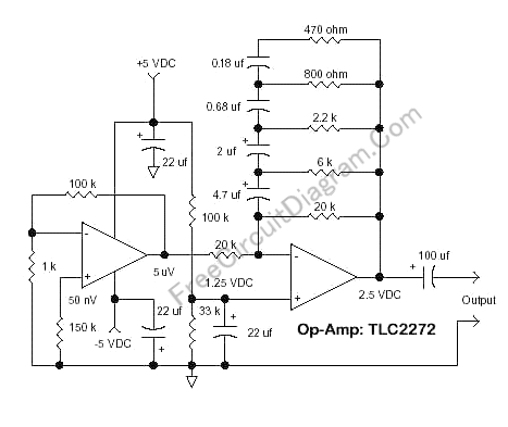
The circuit’s schematic diagram shown in the figure below is a flicker noise generator, an implementation of flicker noise analog modeling presented in NBS technical note #604, “Efficient Numerical and Analog Modeling of Flicker Noise Processes” by J.A. Barnes and Stephen Jarvis, Jr. With the component values shown the schematic diagram,  the circuit will give a 1/f noise slope from […]

Read more

Voltage-Current(V/I) Curve Tracer

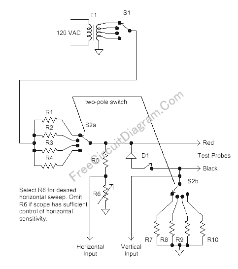
Voltage-Current curve tracer is very important tools for components ant circuits troubleshooting. This circuit need an oscilloscope with X-Y inputs to display the curve. This circuit provide adjustment for both peak-to-peak voltage and the current limiter. The peak-to-peak voltage selected using different voltage taps of the transformer, and the current limiter is selected by different series resistor. An optional diode […]

Read more
1 29 30 31 32 33 40