Sine Wave Oscillator Circuit Using Phase Shifter
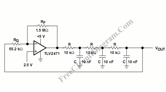
Sine wave oscillator can be implemented using Wien-Bridge oscillator like in our previous sine wave oscillator circuit, but now we present another method of generating sine wave signal. Using phase shifter, we can build a simple sine wave generator, as shown in the schematic diagram below: Sine wave oscillator using phase shifter has lower distortion than Wien-Bridge oscillator, coupled with […]

Read more
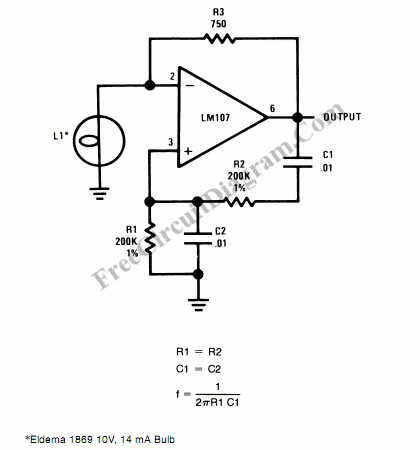
Wien-Bridge Oscillator Using Incandescent lamp Stabilizer

Incandescent lamp has been used to reduce harmonic distortion in sine oscillator circuit. The nonlinear resistance characteristic of the lamp filament help the circuit to shape the signal to approximate the ideal sine wave. Here is the classic Wien-bridge oscillator circuit using the incandescent lamp: You can change the frequency of the oscillator by modifying the R1 (and R2), or […]

Read more

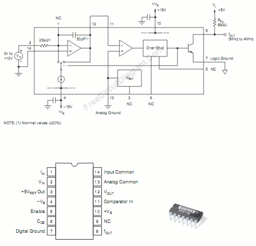
VFC110: Single Chip High-Frequency Voltage-to-Frequency Converter (VFC)

Using VFC110 chip, we can build a high frequency voltage-to-frequency converter. The features of this chip include the capability of high frequency operation, disable function, and an on-board precision 5V reference. This precision reference can be used to provide reference for offsetting the VFC transfer function, as well as provide transducer or bridge excitation. As well as shutting off the […]

Read more

Simple Stand-Alone Voltage-to-Frequency Converter Using LM231/LM331

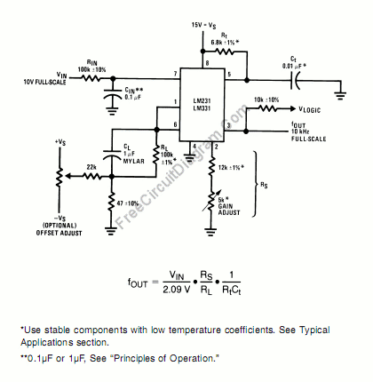
Using LM231/331 chip, we can build a low-cost voltage-to-frequency converter, ideal for analog-to-digital conversion, frequency-to-voltage conversion, long-term integration, linear frequency modulation-demodulation, and many other functions.  When it’s used as voltage-to-frequency converter, the output will be a pulse train with frequency linearly equal to the applied input voltage. For higher level of accuracy against temperature drift, LM231A/LM331A can be used, let’s […]

Read more

Three Op-Amps Instrumentation Amplifier: Easy Gain Adjustment Design

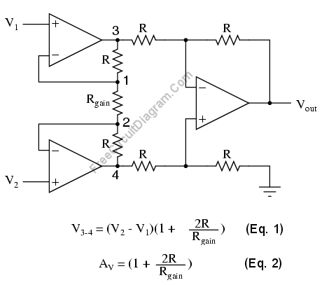
Although this circuit use more resistor components than in basic standard three op-amps instrumentation amplifier circuit, this circuit has the benefit of easy gain adjustment with only one control resistor. Because the easy gain adjustment feature, this circuit topology has been used inside a single chip instrumentation amplifier ic. The figure below shows the schematic diagram of the circuit. Though […]

Read more

Two Op-Amps Instrumentation Amplifier

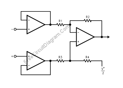
For standard instrumentation amplifier, a three op-amps instrumentation amplifier circuit is common, but if you need smaller component count and lower cost, you can use just two op-amps for the same function: a high impedance and good CMRR for sensor pre-amplification and buffering. Here is the circuit’s schematic duiagram: A two-op-amp instrumentation amplifier can also be used to make a […]

Read more

Three Op-Amps Instrumentation Amplifier

Using LMV721/722 or any other high impedance op-amps, you can build an instrumentation amplifier using standard three op-amps instrumentation amplifier circuit. The figure below shows the circuit’s schematic diagram. The final stage of this instrumentation amplifier is a differential-input, differential-output amplifier, with two voltage followers feed its inputs. These two voltage followers assure that the input impedance is over 100M. […]

Read more
1 15 16 17 18 19 20