Tachometer Circuit with Single Transistor
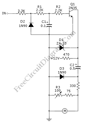
A schematic diagram of  simple tachometer circuit is shown below. Using only a single transistor as the active component, this tachometer would probably be the simplest one. The input of this circuit can be picked up from ignition pickup coil,  or other wiring that gives ignition wave-form. This tachometer circuit works for 0 to 6,000 rpm. R3 is used for […]

Read more
Sound-Controlled Relay

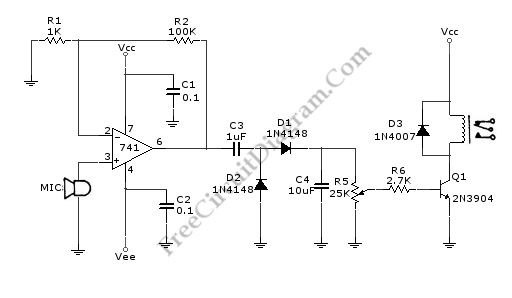
This is a relay circuit that detect the presence of sound to activate the relay. You can use this sound-controlled relay as voice operated switch, light control, toys, or any other application that can be controlled by a switch. Just replace the switch with  this relay and now you have a sound-controlled device. This circuit uses a 741 operational amplifier […]

Read more

Touch Switch Monostable/Timer with 555 IC

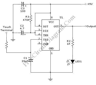
A schematic diagram of a touch switch circuit is shown below. This circuit consist of timer, one shoot multivibrator and touch terminal. As timer, this circuit uses 555 timer which is connected to one-shot multivibrator. The touch terminal is used to trigger this circuit. The output of this  circuit can be used to drive a power transistor, CMOS circuitry, hexFET […]

Read more

2 Phase and 3 Phase Motor Drivers

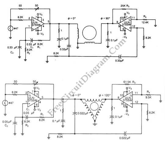
The schematic diagram below show 2-phase and 3-phase motor driver circuits. This circuit can used to drive an AC motor because this circuit has an integrated power operational amplifier, built-in power-output stage and high amplification factor. The needed AC signal is produced by the op amp that is configured as oscillator. The motor is driven by the high-current that is […]

Read more

Touch Switch Data Input Interface

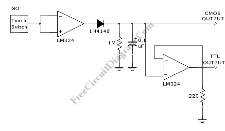
This is an interface circuit for digital data input. This circuit consist of touch button, op-amp, diode, capacitor and resistors. Any conductor surface can be used as the touch probe, such as a machine-screw head having comparable area around 0.5-inch-square or similar area of any pattern on printed-circuit board. This circuit need a DC power supply that is produced by […]

Read more

LM10 Battery Voltage Threshold Indicator

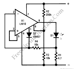
A battery threshold indicator circuit shown in the schematic diagram below has current regulation mechanism in driving the LED. A sufficient current should be satisfied at the minimum voltage but no excessive current when the voltage is at the highest level. Balance pin (5) is used as the reference  voltage for regulating the current. This pin generate 23 mV, which […]

Read more

Series-Wound Direction And Speed Motor Control

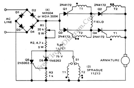
This is a motor controller circuit that  control the speed  and direction of series-wound Motors. This circuit employs silicon controlled rectifiers (SCR) Q1-Q4, that are triggered in diagonal pairs. The switch St is used to control which pair is turned on because either coupling transformer T2  or coupling transformer T1 is connected to a pulsing circuit by this switch. Here […]

Read more
1 2 3 4 22