Pulse Position Modulator

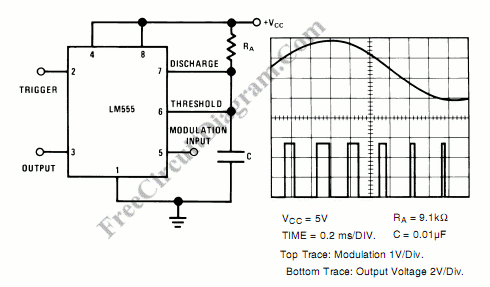
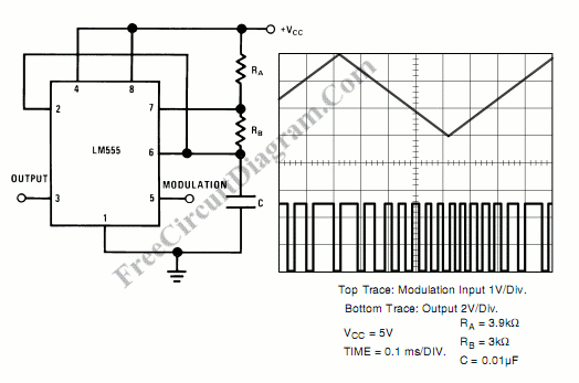
Pulse position modulator can be easily built using 555 IC. Here is the schematic diagram of the circuit: Pulse position modulator modulate the on-period while keeping the fixed off-period. Pulse position modulation might substitute pulse-width modulation in some application. The main difference between pulse position modulation (PPM)  and pulse width modulation (PWM)  is that  unlike PWM, PPM doesn’t keep constant […]

Read more

LED Flasher Using 555 IC

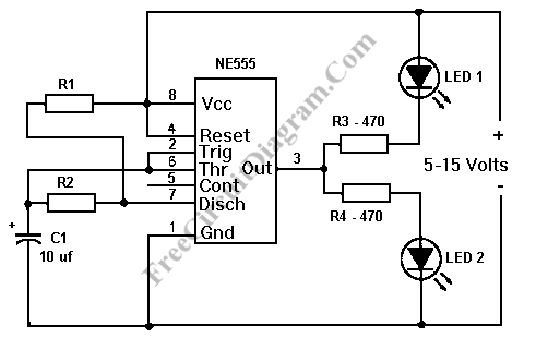
This LED flasher give similar circuit with the previous transistor LED flasher, but this circuit use a 555  integrated circuit chip as the active component. Here is the schematic diagram of the LED flasher circuit: This circuit gives alternating LED flashing, but with different flashing period between LED 1 and LED 2. The ON period of the LED 1 is […]

Read more

LED Flasher Circuit Using Transistors

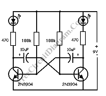
Classic LED Flasher Circuit This LED flasher circuit is a classic two transistor flip flop. This flasher circuit is very popular and it’s usually the first circuit to build when starting electronic circuit building hobby. Here is the schematic diagram of the famous LED flasher circuit: How LED Flasher Circuit Works The circuit consist of two transistors, two capacitors, four […]

Read more

Crystal Tester

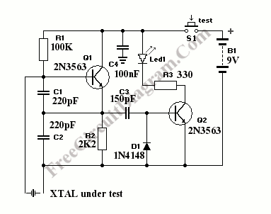
A crystal tester circuit is very simple, it contains only oscillator and detector inside. This crystal tester circuit uses one transistor for the oscillator and one transistor for the detector. Here is the schematic diagram of the circuit: The mechanism of this crystal tester is very simple. If a good crystal is connected to the test lead, the oscillator will […]

Read more

Wailing Alarm Siren

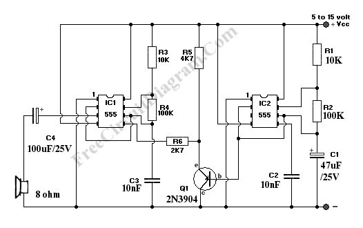
This alarm siren circuit produce warbling sound, you can use it in your toys or  in security alarm.  The circuit use two 555 IC oscillator. In this alarm siren circuit, the first oscillator is employed to produce audio frequency. The second oscillator is employed to produce a modulating signal. This modulating signal make this alarm siren generates warbling sound. Here […]

Read more

Dimmer Switch

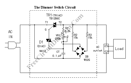
This circuit is similar with our previous dimmer circuit, but the gate control is full-wave rectified using diode bridge. This circuit can be used to replace electric switch for your incandescent lamp, brushed motor, soldering iron or heater. Here is the schematic diagram of the dimmer switch: Please note that his dimmer switch can only work on AC voltage, it’s […]

Read more
1 2 3 4