Summing Amplifier with Op-Amp
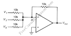
One of inverting amplifier application is for summing several electric signals. The output of this circuit produce the sums of the input voltages.  We can use both positive or negative voltage for the inputs. The input resistors doesn’t have to be  same values. The input can be expanded to several digits. Since the point X is a virtual ground, the […]

Read more
Differential Amplifier with Op-Amp

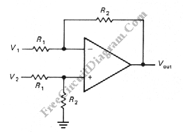
The schematic diagram below shows a differential amplifier circuit. This circuit is used to get a common-mode rejection ratios. This circuit need a precise resistor matching to get common-mode rejection ratios because the current source uses matched resistor ratios. Here is the circuit: The gain of this circuit is determined by following equation: gain=R2/R1 The Vout is determined by following […]

Read more

Photovoltaic (Solar Cell) Current To Voltage Converter

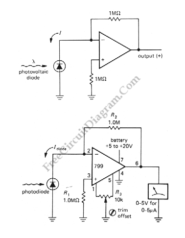
The simplest I to V converter is the humble resistor. However, presenting a nonzero impedance to the source of input current is the disadvantage of the humble resistor. If the device providing the input current has very little compliance or does not produce a constant current as the output voltages changes, this can be fatal. A photovoltaic cell is a […]

Read more

Op-Amp Voltage Follower With Bootstrap

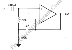
The bias path can compromise the high input impedance you would otherwise get with an op-amp as with transistors amplifiers. This particularly with ac-coupled inputs where a resistor to ground is mandatory. The bootstrap circuit shown below is a possible solution if that is a problem. The 1mF capacitor makes the upper 100k resistor look like a high impedance current […]

Read more

Digitally Controlled Dual Polarity Amplifier

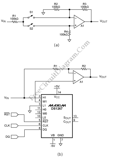
This schematic diagram below shows a Digitally Controlled Dual Polarity Amplifier circuit. The circuit (a) can give a means of amplifying a signal either in non inverting and inverting mode. When S2 is off and S1 is on, the noninverting input of the op amp is fed by the signal. The circuit behaves as a regular inverting amplifier, When switch  […]

Read more

Wheatston Bridge PWM Signal Conditioner

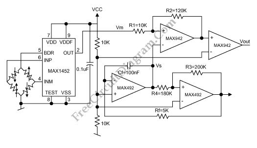
This is a schematic diagram of a Wheatston Bridge PWM Signal Conditioner circuit. This circuit uses the MAX1452 signal conditioner. A ratiometric compensated output for the Wheatstone Bridge is generated by the MAX1452. Then the output of the Wheatston bridge is converted to a PWM output. the PWM-output duty cycle changes accordingly, as the MAX1452 output changes with pressure. the […]

Read more

Anti-Log Converter

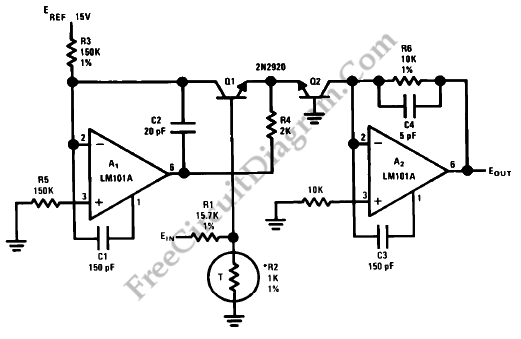
Anti-log or exponential generation is simply a matter of rearranging the logarithmic circuitry. The circuit diagram below shows the circuitry of the log converted to generate an exponential output from a linear input. The emitter of Q2 in proportion to the input voltage is driven by amplifier A1 in conjunction with transistor Q1. The collector current of Q2 varies exponentially […]

Read more
1 2 3 4