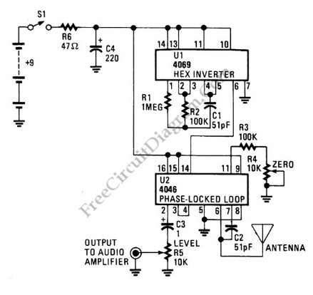
Simple Theremin with Inverter Gates

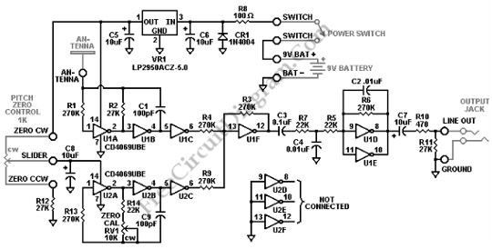
This simple but complete Theremin circuit is constructed using only two inverter chip plus one regulator IC. This Theremin circuit consist of five functional blocks: power supply regulator, hand controlled oscillator, null oscillator, mixer, and filter. Here is the complete schematic diagram:     Voltage Regulator and Circuit Protector The power supply regulator consist of LP2950 regulator IC, which stabilize […]

Read more

Optical Theremin

Normally, Theremin works by detecting hand proximity using capacitive coupling method. A Theremin circuit shown in the schematic diagram below use different method to control the pitch. The oscillator of this tone generator, both the volume and frequency  are controlled using LDRs, a light sensitive electronic component, so we can call this circuit an optical Theremin.  Look at the following […]

Read more

Simple Digital Theremin

Theremin circuit shown in this schematic diagram uses digital component, so we can call it a digital Theremin. This circuit employs  logic inverter 74C04 or CD4069 hex inverter and CD4046 phase-locked-loop (PLL) IC. The CD4069 logic inverter is operated as a fixed-frequency oscillator with  frequency around 100kHz. The CD4046 is operated as a variable frequency oscillator which is adjustable around […]

Read more

Single Chip Theremin Circuit

This schematic diagram show a single chip Theremin circuit.  Theremin is an electronic music instrument which sense hand movement to control the tones/frequency.  This Theremin circuit uses two separate Colpitts LC oscillators to produce a beat frequency. The frequencies of  two Colpitts LC oscillators are mixed and then rectified. This rectification  demodulate the mixed signal to get the beat frequency […]

Read more