Voltage-Current(V/I) Curve Tracer

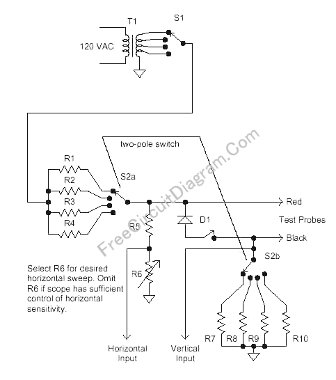
Voltage-Current curve tracer is very important tools for components ant circuits troubleshooting. This circuit need an oscilloscope with X-Y inputs to display the curve. This circuit provide adjustment for both peak-to-peak voltage and the current limiter. The peak-to-peak voltage selected using different voltage taps of the transformer, and the current limiter is selected by different series resistor. An optional diode is provided to limit the negative swing at about 0.7 volt, possibly needed when testing some device that cannot stand with reverse voltage. No critical need for the voltage and current range, as you can see there are no problem with many other version with no such adjustment.
You can use various transformer voltage as this is not critical, but limiting the voltage at 24 Volt is a good idea to prevent shock hazard.
For resistor pairs R1 & R7, R2 & R8, R3 & R9, R4 & R10, note that these resistor pairs have the ratio of 1000:1, for example if R1=100 ohm then R7 is 0.1 ohm. The first resistor in the pair is used to limit the current, and the second one is used to sense the current. You can use 100R/10W for R1, 1K/1W for R2, 10K/0.25W for R3, and 100K/0.25W for R4. For the current sensing use 0.1R, 1R, 10R, and 100R for R7-R10. The power dissipation would be small for these current sensing resistors, so almost any wattage would be suitable.
Around 100k is fine for R5 and R6, but any fairly high values will work here. These resistors adjust the amplitude for the scope’s horizontal input and can be omitted if the scope has good horizontal gain control. This adjustment is provided because some scopes just have one or two gain settings.
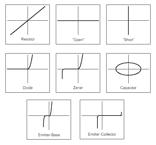
D1 is a silicon diode that capable of handling the maximum test current and voltage. A 1N4002 would work fine for most applications. When the diode activeated by closing the switch, it will limit the negative swing to around 0.7 volt, this is useful to test any device which can’t withstand more than 0.7-1V reversed voltage. The figure below shows some voltage-current curve trace for popular devices.
[Circuit’s schematic diagram source: techlib.com]
