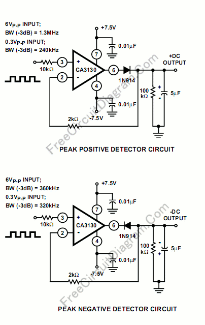
Implementing peak-detector circuits is very easy with the CA3130, as shown in schematic diagram of this circuit. The figure below shows the schematic diagram of the peak detector circuit. The upper section is peak-positive and the lower section is peak-negative circuit.

peak detector ca3130 circuit schematic

Please note that with large-signal inputs, the bandwidth of the peak-negative circuit is much less than that of the peak-positive circuit. In this case, the second stage of the CA3130 limits the bandwidth. The time constant of peak-holding-time or peak-decay-time is determined by the 100k resistor and the 5uF capacitor, you can modify their values for different setting of this peak detector circuit. [Circuit's schematic diagram source: Harris Semiconductor Application Note]


Possibly Related Articles:

  • Single Transistor Half-Wave Peak Detector Circuit
    Using only a single transistor and few passive components, you can build a fairly sensitive peak detector. circuit This peak detector circuit is suitable for audio application, since the average...
  • Simple 555 Switching Circuit Provides Negative Supply from Single Positive Supply
    If you need a negative supply for op-amp or just need negative bias voltage while operating from a single supply voltage (for battery operation for example), this circuit helps providing...
  • Fast Peak Detector
    Fast peak detector requires special amplifier features. The output stage must have high slew rate to keep up with the intermediate stages of the amplifier. This condition causes either a...
  • Precision Half-Wave Peak Detector
    A simple half-wave peak detector using a single transistor is very compact and low cost, but if the application require precise detection for signal under 100mV then that circuit become...
  • Open Loop Fast Peak Detector
    A fast peak detector similar but faster than previous peak detector, can be implemented using open loop configuration. Here is the schematic diagram of the circuit: In thisĀ  design, D1...