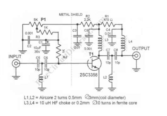
UHF antenna booster can be used for better reception, especially when you’re far from TV station / relay transmitter. This UHF antenna booster works in 400-850 MHz range. Here is the circuit diagram of the UHF antenna booster:

The circuit use only one transistor, but it gives you 10 to 15 dB amplification, enough for many situation. The most important part is that the transistor circuitry should be shielded from the input circuitry, as shown in the schematic diagram by the dashed line. This ircuit is powered via the signal cable, since the antenna booster circuit must be wired as close as possible to the antenna. This is very important since the amplifier should amplify the signal acquired by the antenna, not the noise picked by the cable from the antenna to the circuit. The antenna and the booster circuit can be installed above your house’s roof. Long 75 ohm coaxial cable can be drawn from the this booster circuit output to the power supply unit close to TV set.

Just insert a 50-10o uH inductor or RF choke between the output cable and the power supply. Tap the output signal from the output cable using a small 100pF ceramic capacitor to block the DC voltage from the power supply. Adjust P1 to get the best reception, and this should set the working current consumption to around 5-15 mA.
Possibly Related Articles:
- AM/FM Antenna Booster
This antenna booster circuit can be used to amplify the weak signal received by the antenna. Antenna for AM/FM is usually not tuned for the optimal dimension of 1/4 wavelength,... - Active Antenna With Gain (Booster)
This is an active antenna circuit with gain. This circuit is used to bost the signal. This circuit is made from a few transistors and other components. This circuit can... - VHF-UHF Antenna Amplifier (Booster) 40-500MHz
This amplifier has VHF (very high frequency) and UHF (ultra high frequency) response, you can use it for receiver booster for example. Here is the schematic diagram of the circuit:... - How to Pre-Tune a Ham Radio Antenna – Video Tutorial
This is video about how to pretune a ham radio antenna. This video shows how to tune a ham radio. In this video, the antenna is tuned to make sure... - Stereo VU Booster Circuit using Transistors
This is a Stereo VU Booster circuit. In this circuit, shown in the schematic diagram, transistor FCS9014 is used. Actually you can use almost any type of small signal NPN... - Discrete Bass Booster Circuit
This bass booster circuit can be used filter the input signal as part of internal circuit of an active subwoofer circuit. This circuit is not only boost the bass (low)... - How Find The Resonance Frequency and Tune Antenna Wave Traps – Video Tutorial
This is a video that provide the information about How find the resonance frequency and tune antenna wave traps. To find the resonance frequency we can use the wave traps.... - Transformerless Voltage Booster Circuit: A DC-DC Step-Up Switching Regulator Using Transistors
A DC-to-DC step-up converter is traditionally implemented using transformer, working by converting the DC voltage to AC Voltage, step-up it using transformer, then rectify and filter the transformer’s output to ... - Automatic AF-RF Probe
Using this automatic probe, you can see measure both audio signal (AF) and radio signal (RF). If audio signal is being measured, the path of the signal is via C1.... - Cable Reflection Tester
This is a Cable Reflection Tester circuit. This circuit can be used to check coax cable runs for shorts or even impedance mismatches. This circuit will send a pulse down... - Another RF Field Strength Meter
This circuit is another radio frequency (rf) field strength meter, similar with our previous field strength meter circuit, but with lower supply voltage (only a single cell 1.5V battery). Here... - AM Radio Receiver Circuit Using TDA 1072AT IC
TDA 1072AT is a special purpose integrated circuit for AM radio receiver from Philips Semiconductors. The integrated circuit is designed for mains-fed home receivers and car radios. The voltage-controlled oscillator...
| 

