Video Switch

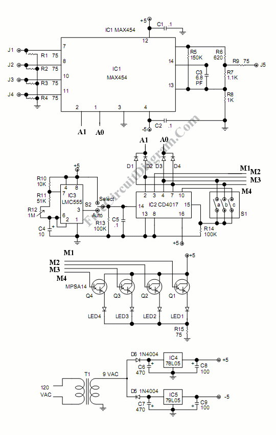
As the price of security camera going down, installing the camera in the shop, office, or even in home becomes economically feasible. Providing a dedicated monitor for every installed camera is not efficient, and your CRT monitor might suffer phosphor burn if it used to display static image from only one camera. To display 1, 2, 3, or 4 cameras in one monitor, you need a video switcher circuit. Here is the schematic diagram of the circuit:

The core of this video switcher is MAX454 video multiplexer-amplifier from MAXIM. Care must be taken when designing the video signal path around this chip. Ground plane or track can be inserted between video signal channels to prevent crosstalk and noise interference. Using socket for IC is bad idea, you should solder the chip directly to the PCB. You can see a CD4017 sequencer driving the channel indicators (LED1-LED4). The output of this sequencer is not only drive the indicators, but also decoded to 2 bit binary data by D1…D4 to address the MAX454 multiplexer.
Peter Kevelam wrote a comment on this circuit’s schematic diagram:
The circuit of the video-switch does not work in this way.
Listen:
The output of IC1 MAX454 is point (14). The output-signal goes from (14) right to the top of C3 and then it stops. It cann’t come to R9 through 75Ohm to the end-output J5. There is missing a line between the top of C3 and the crosspoint R6/R7/R9. So there must come a line(thread) between the top of C3 and the crosspoint R6/R7/R9. Then it is working.