Automatic Battery Backup

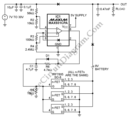
The diode-OR connection is the simplest link between backup battery and a main supply with a load. But, when the battery voltage is greater than main supply voltage, it will not work. To solve this problem we can use the circuit below. Here is the circuit :

This circuit has the backup supply of 9V battery and main switch-mode supply voltage ranges from 7V to 30V. It uses the MAX931 which is an ultra-low-power comparator with a 1.182V bandgap reference. When it is used in normal condition, the battery’s negative terminal floats, the three parallel-connected n-channel FETs are off, and the comparator output is low. The n-FETs will turning on, the negative terminal of the battery will be grounded and the comparator’s output goes high when the the main voltage declines to 7.4V.
To eliminate the a supply-rail glitch that would otherwise happen when switching from the battery to the main supply, the delay was used. It can be done by using the R6, C1, and D1. An unacceptable reset in the system’s microcontroller can be occurred while the glitches. For proper operation, the value of R3 and R4 should set the hysteresis in the MAX931 to 800mV. [Source: maxim-ic.com]