Permanent Magnet Motor Control with SCR
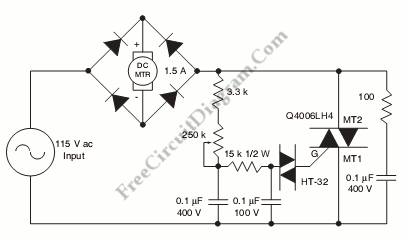
This is a schematic diagram of Permanent Magnet Motor Control circuit. This circuit is used to control the permanent magnet control. This circuit uses alternistor triac to enhance commutation characteristics because the PM motor is a generator where the standard triac difficult to commutate properly. The full-wave DC rectification is needed for PM motors. Here is the schematic diagram of the circuit:
The alternistor triac is connected with AC input side of the rectifier bridge in series connection. The most critical part on the installation of SCR on the DC side of bridge is when dealing with delayed turn-on and timing near the end of the half cycle.This circuit gives wide range control, so the alternistor triac can be triggered at low motor speed or small conduction. The alternistors and rectifiers have similar voltage ratings. All of them based on actual motor load and line voltage requirements. [Circuit’s schematic diagram source: littlefuse.com]