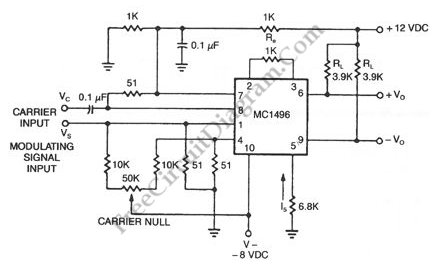
When we modulate a carrier signal with amplitude modulation, there will be four frequency components as the result. The first is the modulating signal itself, the second is the frequency carrier, the the latest two are the difference and the sum of the carrier and the modulating signal.  The spectrum of these frequencies can be seen using frequency analyzer.  In radio transmission, the modulating frequency components is completely filtered out since the frequency is far lower than the other three. To increase the power efficiency, double sideband suppressed carrier modulator (DSB-SC) remove the carrier frequency part, so the transmitted frequencies consist only the side bands: the sum and the difference.  In the schematic diagram below, a double-sideband suppressed-carrier modulator circuit is presented. There is no carrier appear in the output because of the basic current. The Carrier amount appear in at the output can be controlled by adding offsets to the carrier differential pairs. The function of the modulation signal-AM modulation is the amplitude.

Double Sideband Suppressed Carrier Modulator circuit schematic


Possibly Related Articles:

  • Superlinear FM (Frequency Modulator)
    Designing various electronic circuit system (synthesizer, modem, decoder, data converter, etc) of ten need a frequency modulator subsystem. An FM modulator is very easy to build with TC9400 since the...
  • Pulse Width Modulator Using 555 IC
    Pulse width modulator produce a PWM signal, a pulse with a constant frequency but with the duty cycle vary according to a modulating signal. Here is the schematic diagram of...
  • Pulse Position Modulator
    Pulse position modulator can be easily built using 555 IC. Here is the schematic diagram of the circuit: Pulse position modulator modulate the on-period while keeping the fixed off-period. Pulse...
  • How to Make Double Sided PCB Using Toner Transfer – Part 2 – Video Tutorial
    This is double sided PCB video tutorial part 2. This video shows step by step how to make double sided PCB. After we transfer the printed circuit into the board,...
  • How to Make Double Sided PCB Using Toner Transfer – Part 1 – Video Tutorial
    This is double sided PCB video tutorial part 1. This video shows step by step how to make double sided PCB using toner transfer method. This video uses PCB fab...
  • Monitoring Off-Air Condition
    The circuit of off-air monitor for SSB transmitter can be built by using combination of detector product with the crystal oscillator. This circuit is used for testing the audio at...
  • 2 Transistors Mini MW Transmitter
    This is a Mini MW (Medium Wave) Transmitter circuit. This circuit consist of combination of transistors SA103 and SA101. Those transistors is used as oscillator and modulation signal amplifier. Here...
  • Digital IC Transmits Both FM and AM Simultaneously
    The transmitters that either working in FM or in AM is familiar. This is transmitters circuit that can transmit both FM and AM signal simultaneously at two different frequencies FM...
  • Small AM Transmitter Circuit: Using Logic Gates!
    For you who has failed to build  radio transmitters, this circuit worth a try. This circuit uses 74HC14 hex Schmidt trigger as the oscillator, and you can choose to use...
  • Automatic AF-RF Probe
    Using this automatic probe, you can see measure both audio signal  (AF) and radio signal (RF). If audio signal is being measured, the path of the signal is via C1....
  • Video Switch
    As the price of security camera going down, installing the camera in the shop, office, or even in home becomes economically feasible. Providing a dedicated monitor for every installed camera...
  • Another RF Field Strength Meter
    This circuit is another radio frequency (rf) field strength meter, similar with our previous field strength meter circuit, but with lower supply voltage (only a single cell 1.5V battery). Here...