Main Power-Battery Backup Switcher
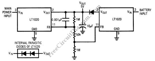
For critical operation, the power loss can be unacceptable. It might be costly if a financial data is lost from the memory in the middle of point of sale transaction, or even it can be deadly if some life support devices fails during critical surgery. The schematic diagram presented here is a battery backup regulator circuit, useful for memory or other low power (battery operated) but critical circuit (must continue operation on power-line failure). The one LT020 will not conduct in under line-powered condition, made possible by means of of feedback string’s arrangement. In case of main power failure, the battery-driven LT1020 will turn on and maintain the load, when the line LT1020 go off because the line goes down.