Simple Continuity Tester with Classic Flip-Flop Circuit
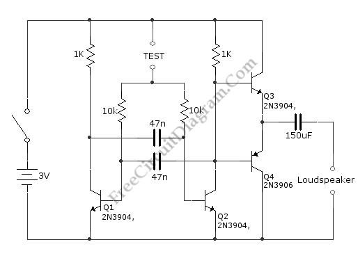
The requirement of a continuity tester is that its current should be small enough to not destroy the tested circuit. This simple circuit inject not more than 0.6 mA current into the tested path in the tested circuit. The schematic diagram describes all the circuitry of the circuit. This circuit is used to test if two point is electrically connected by sounding a tone, which the pitch is inversely proportional to the resistance of the tested points. This circuit is designed for high resistance circuit, but however, this circuit can be used for low-resistance circuits. The multi-vibrator’s frequency is influenced by the resistance between the tested points, and this multivibrator is formed by classic flip-flop circuit Q2 and Q1. The output stage Q4 and Q3 drive a telephone earpiece or a small loudspeaker.