Direct Coupled Discrete Astable Multivibrator
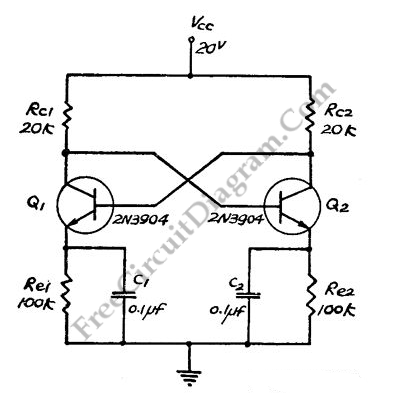
This flip-flop circuit  is a free running/astable multivibrator one,  with bases and collector of both emitter biased transistor are directly coupled to each other.  Switching action is supported by means of capacitor in each emitter circuit.  This configuration produce a triangle waves at emitters. Since neither transistor can remain permanently cut off, then a free running oscillation will be generated. […]

Read more
LM3900 Audio Mixer

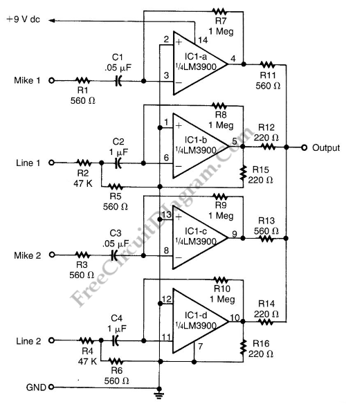
This audio mixer circuit doesn’t use a low impedance input to mix no ideal  sources, but use many amplifiers to provide  ideal sources before mixed through simple resistors. Ideal source means a sources with low impedances, make the interaction between signals in the output doesn’t affect the input.   Please note that this mixer circuit has high impedance output, so you’ll […]

Read more

AM Radio Receiver Circuit Employs FM IC Chip

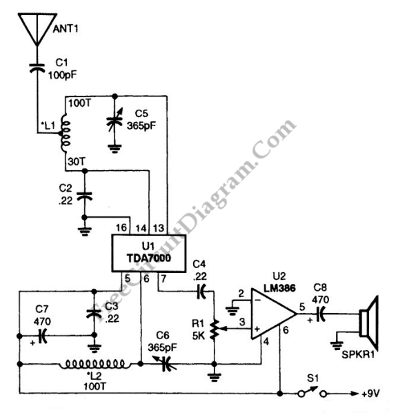
This AM receiver consists of a TDA7000 single-chip FM receiver (U1) as the main radio component,  and an LM386  chip for low-voltage audio-power amplifier (U2) circuit. The receiving coils are  hand-wound coils (L1 and L2), and a few additional components.  This coils, together with the variable capacitor, is chosen to match the AM frequency. To wind your won coil, L1 […]

Read more

Power Saver for Relays

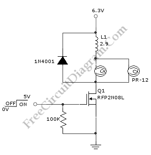
Relays are normally operated at current level where it can initiate the mechanical metal contactors movement. After contacts has been established, the current level needed to keep the conductor plates stay attached is actually smaller than the current to initiate it. This power saver circuit seems to have opposite mechanism of surge protector. This circuit provide surge current to initiate […]

Read more

Discrete Sliding Tone (Frequency Ramp) Doorbell

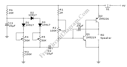
This doorbell circuit produces a low tone that will slide up to higher frequency. The equivalent total resistance connected between the base of Q1 and ground (Rbg) , and coupling capacitor  C1  determines the AF oscillator’s frequency. The resistance (Rbg) is equal to (R2+R1)R3.  Here is the schematic diagram of the circuit: The R2 is used to set the initial […]

Read more