Three Op-Amps Instrumentation Amplifier
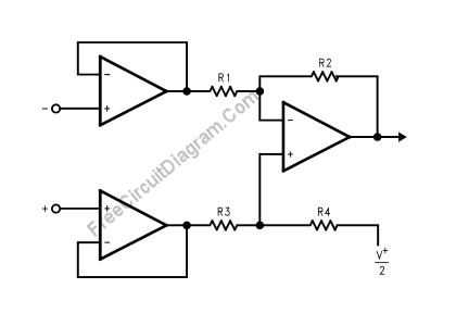
Using LMV721/722 or any other high impedance op-amps, you can build an instrumentation amplifier using standard three op-amps instrumentation amplifier circuit. The figure below shows the circuit’s schematic diagram. The final stage of this instrumentation amplifier is a differential-input, differential-output amplifier, with two voltage followers feed its inputs. These two voltage followers assure that the input impedance is over 100M. […]

Read more
Single Chip Single Supply Instrumentation Amplifier

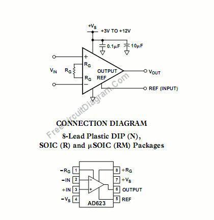
The AD623 is a single chip instrumentation amplifier. The internal circuit is based on a modified classic three op amp approach to assure single or dual supply operation even at common-mode voltages at the negative supply rail. Some key features are: Low voltage offsets, input and output, as well as absolute gain accuracy, and one external resistor to set the […]

Read more

LM1894: Single Chip Dynamic Noise Reduction System (DNR)

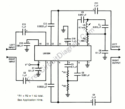
The LM1894 is a stereo noise reduction circuit suitable for audio playback application. The DNR system is non-complementary, meaning that it does not require encoded source signal. The system is compatible with almost all prerecorded tapes and FM broadcasts. This noise reduction system uses  psycho-acoustic masking and an adaptive bandwidth filtering to achieve 10 dB noise reduction.  This DNR would […]

Read more

Low-Drop-Out (LDO) Low-Voltage Linear Regulator Using NCP2860 IC

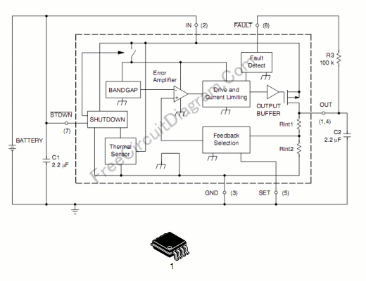
This low drop out (LDO) voltage regulator need only few components, with very low noise and very low drop-out voltage. The circuit illustrated in the schematic diagram below gives a fixed 2.77 volt output, but this output voltage can be adjusted using two additional resistors. This circuit capable to supply 300 mA load from 3.0 V to 6.0 V input.  […]

Read more

Positive and Negative Peak Detector Circuit Using CA3130 Op-Amp

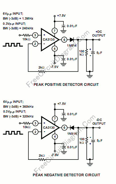
Implementing peak-detector circuits is very easy with the CA3130, as shown in schematic diagram of this circuit. The figure below shows the schematic diagram of the peak detector circuit. The upper section is peak-positive and the lower section is peak-negative circuit. Please note that with large-signal inputs, the bandwidth of the peak-negative circuit is much less than that of the […]

Read more

Single Supply Precise Full Wave Rectifier Using CA3140 Op-Amp

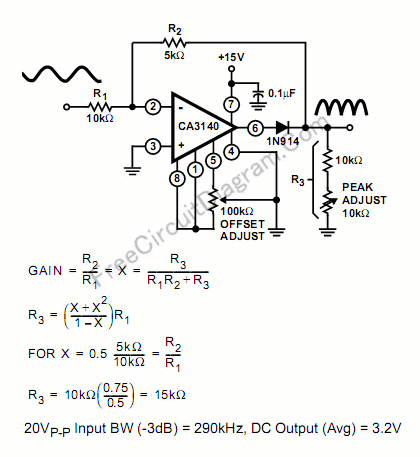
The schematic diagram below describe a precise full-wave rectifier circuit. The circuit needs only a single supply, make it suitable for battery operated devices. During the positive cycle of the input, the signal is directly fed through the feedback network to the output, give the transfer function of Vout=R3/(R1+R2+R3). At the positive cycle of the input, the diode 1N914 disconnect […]

Read more
1 27 28 29 30 31 40