Power Saver for Relays

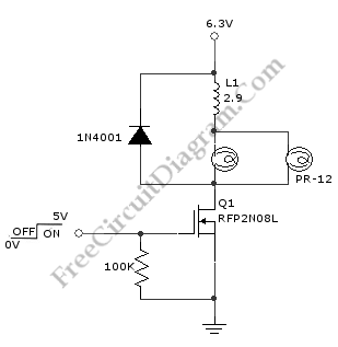
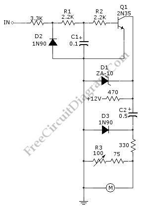
Relays are normally operated at current level where it can initiate the mechanical metal contactors movement. After contacts has been established, the current level needed to keep the conductor plates stay attached is actually smaller than the current to initiate it. This power saver circuit seems to have opposite mechanism of surge protector. This circuit provide surge current to initiate […]

Read more

Discrete Sliding Tone (Frequency Ramp) Doorbell

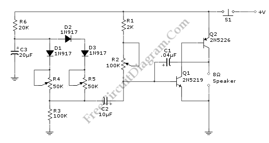
This doorbell circuit produces a low tone that will slide up to higher frequency. The equivalent total resistance connected between the base of Q1 and ground (Rbg) , and coupling capacitor  C1  determines the AF oscillator’s frequency. The resistance (Rbg) is equal to (R2+R1)R3.  Here is the schematic diagram of the circuit: The R2 is used to set the initial […]

Read more

True Stereo Indicator Detects L-R Signal Difference

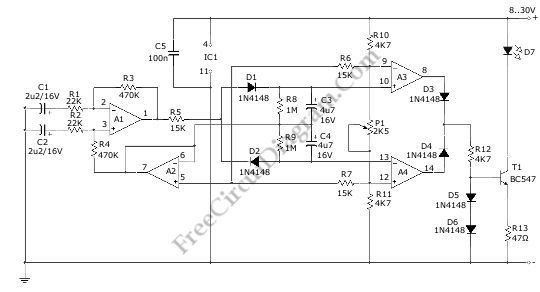
This true stereo indicator is different from what we usually find on FM radio receiver, which is usually a pilot tone detector. A stereo broadcast from FM radio station contain pilot tone, but a presence of pilot tone doesn’t necessarily a stereo broadcast signal since a mono FM transmitter ca broadcast pilot tone as well.  Since this circuit detect the […]

Read more

Tachometer Circuit with Single Transistor

A schematic diagram of  simple tachometer circuit is shown below. Using only a single transistor as the active component, this tachometer would probably be the simplest one. The input of this circuit can be picked up from ignition pickup coil,  or other wiring that gives ignition wave-form. This tachometer circuit works for 0 to 6,000 rpm. R3 is used for […]

Read more

Variable Frequency Switch Mode Regulator

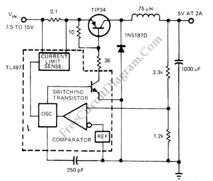
This voltage regulator circuit operates in switch mode. Using the configuration shown in the schematic diagram, this circuit has variable switching frequency, depends on the input voltage and load condition. The core controller of this switching regulator is a TL497 switching regulator controller IC. Here is the schematic diagram of the circuit: When the load is low (draw only small […]

Read more
1 4 5 6 7 8 54