Single Chip Theremin Circuit

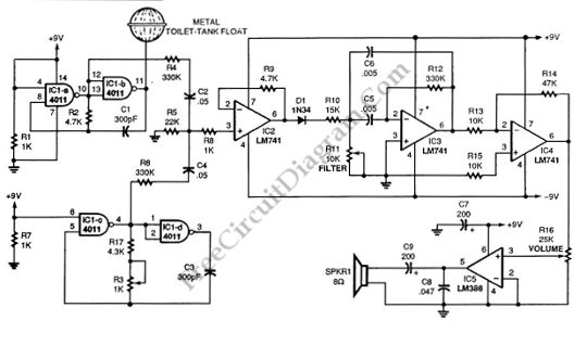
This schematic diagram show a single chip Theremin circuit.  Theremin is an electronic music instrument which sense hand movement to control the tones/frequency.  This Theremin circuit uses two separate Colpitts LC oscillators to produce a beat frequency. The frequencies of  two Colpitts LC oscillators are mixed and then rectified. This rectification  demodulate the mixed signal to get the beat frequency […]

Read more

Touch Switch Monostable/Timer with 555 IC

A schematic diagram of a touch switch circuit is shown below. This circuit consist of timer, one shoot multivibrator and touch terminal. As timer, this circuit uses 555 timer which is connected to one-shot multivibrator. The touch terminal is used to trigger this circuit. The output of this  circuit can be used to drive a power transistor, CMOS circuitry, hexFET […]

Read more

2 Phase and 3 Phase Motor Drivers

The schematic diagram below show 2-phase and 3-phase motor driver circuits. This circuit can used to drive an AC motor because this circuit has an integrated power operational amplifier, built-in power-output stage and high amplification factor. The needed AC signal is produced by the op amp that is configured as oscillator. The motor is driven by the high-current that is […]

Read more

22W Amplifier for 12V Power Supply Systems

This is a 22-W Amplifier circuit that is designed for or 12-V DC power supply Systems. There are many application for  this circuit,  such as in car audio  application. In car electrical  power supply system, the 12V power supply will be provided by the host vehicle’s battery. The capacitor C3 is used to give ripple rejection, since noisy power supply […]

Read more

Versatile Discrete Monostable Multivibrator

This is a versatile discrete monostable circuit. This circuit consist of 2N3819 JFET and 2N3704 transistors. This monostable multivibrator circuit  has additional input to enable or inhibit the function at any time without causing output pulse. The input of this circuit accept a standard digital IC voltage levels. Here is the schematic diagram of the circuit: The  output’s timing cycle […]

Read more

Pulse Width to Analog Voltage Demodulator

This is a schematic diagram of a pulse width to analog demodulator circuit. This circuit is used to demodulate the pulse width to analog voltage level. With input pulse width range of 0 to 1 microsecond, this circuit can produces Output range of 0 to 10 v. The input pulse is integrated and the final value is held until next […]

Read more

Overvoltage Protector with Relay

An overvoltage protector circuit is shown in the schematic diagram below. This circuit will work to disconnect the protected device from the power supply when an overvoltage occurs at the supply. This circuit uses a silicon-controlled rectifier (SCR) and normally-closed 12-V relay, K1. The silicon-controlled rectifier is connected in parallel to 12-V line to monitor for the overvoltage condition. This […]

Read more
1 6 7 8 9 10 54