Retriggerable One Shot with 556 IC

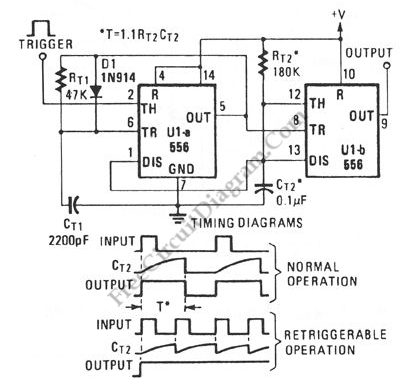
Retriggerable one shot/monostable multivibrator circuit is a flip-flop circuit which give active output when an input is present, and hold the state for a predetermined period before turns to inactive state. The difference between retriggerable and non-retriggerable  is that retriggerable circuit gives period extension when the input is retriggered before the output changes to inactive state.  Here the circuit uses […]

Read more

LF356 Wide Range Current-To-Voltage Converter

Current to voltage converter circuit can be made using a single resistor, it is very simple since any current will naturally develop a voltage when flow through a resistor. Using an active component,  a small developed voltage on a resistor can be accurately measured since we can amplify it to reach a convenient level to be measured. A schematic diagram […]

Read more

Touch Switch Data Input Interface

This is an interface circuit for digital data input. This circuit consist of touch button, op-amp, diode, capacitor and resistors. Any conductor surface can be used as the touch probe, such as a machine-screw head having comparable area around 0.5-inch-square or similar area of any pattern on printed-circuit board. This circuit need a DC power supply that is produced by […]

Read more

Funk (Twang) Guitar Effect Box

This is an audio effect circuit that give extra oscillation to your guitar, percussive, or semi percussive instruments, you can call it a funk box. This  guitar effect circuit is basically a damped oscillator that is set slightly below its critical oscillation point.  The oscillator part is constructed by feeding back the output signal through a bandpass circuit, with the […]

Read more

Capacitor ESR Meter

This is schematic diagram of capacitor ESR meter circuit. ESR is equivalent series resistance, and this parameter is used to express the resistance value of any electronic component that basically is not a resistor. ESR is present on many non-resistor component, such as capacitor, inductor, or semiconductor. The circuit shown in this schematic diagram is used to measure equivalent series […]

Read more

LM10 Battery Voltage Threshold Indicator

A battery threshold indicator circuit shown in the schematic diagram below has current regulation mechanism in driving the LED. A sufficient current should be satisfied at the minimum voltage but no excessive current when the voltage is at the highest level. Balance pin (5) is used as the reference  voltage for regulating the current. This pin generate 23 mV, which […]

Read more

Ring-Around LED Flasher

This schematic diagram shows a ring-around LED flasher circuit. This circuit will turn off two LEDs and turn on the other two until the timing cycle reverses. This circuit can be configured to flash four LEDs in sequential order  by pressing and holding S1 closed until only one of the LEDs is on then releasing it.  Here is the schematic […]

Read more
1 7 8 9 10 11 54