Phase-Shift Meter for Audio Frequency Signal
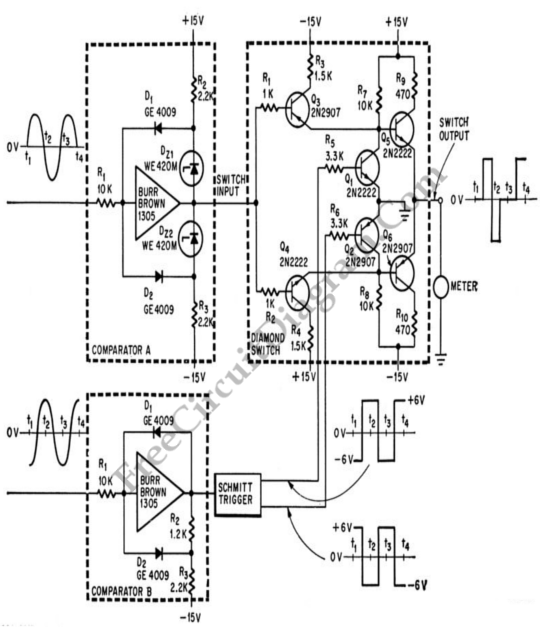
Simple phase shift measurement can be done by squaring both the measured and the reference, then compute the difference of the two signals. The accuracy of the circuit shown in the schematic diagramĀ  below is 1% UP to 2000 cps. This circuit is used in computers and for high speed analog instrumentation. Negative value for zero phase shift is indicated […]

Read more
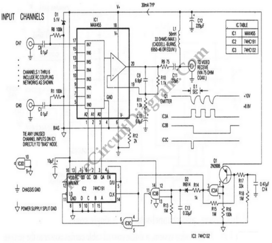
Remote Video System Multiplexer

Combination 8 channel multiplexer and amplifier (IC1) is the heart of the remote multiplexer box in the single coax video system. The MUX baseband video output is coupled by C11 to the coax and the video is decoupled by L1 from dc power arriving on the same line. All circuitry in the multiplexer box is supplied by this power (about […]

Read more

Frequency Shift Keying (FSK) Encoding and Decoding

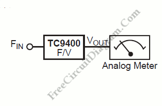
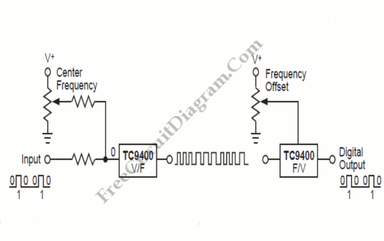
The meaning of Frequency Shift Keying (FSK) is transmitting digital data over a signal path (two wires, telephone lines, AM or FM transmitter). Typically, there are only two signals transmitted. One corresponds to a logical “1”. the other to a logical “1”. These two frequency will be generated by a TC9400 V/F converter when connected as shown below. The V/F […]

Read more

Radio Frequency (RF) Watt Meter

For RF (radio frequency) transmitter experiment, watt meter is useful for optimizing the transmitter circuit. A simple RF watt meter circuit is shown in theĀ  schematic diagram below. Because circuit is not frequency sensitive, calibration is accurate on all HF bands. The sensitivity is affected by meter movement, number of turns in primary coil, and resistive voltage driver. Pots can […]

Read more

10W 2 Meters RF Power Amplifier

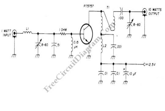
When operating from 12.5 V auto battery, single TRW PT5757 transistor provides 10 W output. L1 is 4 tums No. 20 enamel and L2 is 10 tums No.20. Both, L1 and L2 has 3/32inch inner diameter. T1 is 4:1 transmission-line transformer made from 3-inch length of twisted-pair No. 20 enamel. This circuit can be used to amplify small transmitter (1W), […]

Read more

Op Amp Primer – Video Tutorial

Below is video tutorial about Op Amp primer. Onthis following video tell us about how an Op Amp primer works. The operation of an Op Amp is very simple, just comparing 2 voltages . There are 2 inputs on Op Amp, positive input and negative input. The positive input is called as non-inverting input and the negative input is called […]

Read more
1 6 7 8 9 10 33