High Side Current Sensing for Low Side Switching
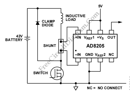
An AD8205 can be used to make a high-side current sense with a low side switch. Besides AD8205, an inductive load (solenoid) and a resistive shunt are added in this circuit. The resistive shunt is placed on high-side and the switch is placed on low-side, so that all current measurements, including the the re-circulation current, can be done because when […]

Read more
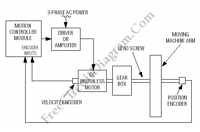
Motion (Motor) Control Servo System Block Diagram

Below is a block diagram of a modern automated systems incorporate closed-loop feedback for motion control. They typically include a servo system that consist of feedback elements and motor driver combined in a manner. This will give accurate and stable control over speed and position. Below is the illustration of the various system-level components of a typical servo system. For […]

Read more

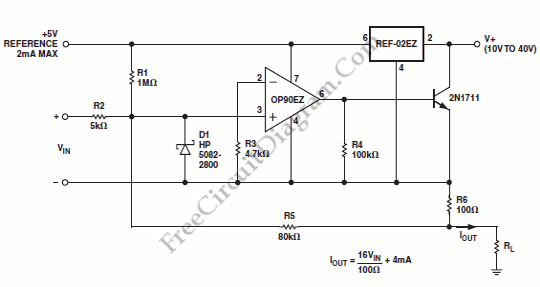
OP90 4 mA to 20 mA Current Loop Transmitter

An output of 4 mA to 20 mA that is linearly proportional to the input voltage is provided by the current transmitter on figure below. Line rejection is 0.0005%/volt and linearity of the transmitter exceeds 0.004%. Here is the schematic diagram of this current loop circuit: The REF-02EZ provides biasing for the current transmitter. The output current is regulated by […]

Read more

Wheatston Bridge PWM Signal Conditioner

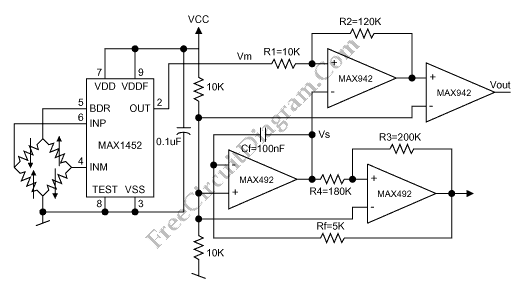
This is a schematic diagram of a Wheatston Bridge PWM Signal Conditioner circuit. This circuit uses the MAX1452 signal conditioner. A ratiometric compensated output for the Wheatstone Bridge is generated by the MAX1452. Then the output of the Wheatston bridge is converted to a PWM output. the PWM-output duty cycle changes accordingly, as the MAX1452 output changes with pressure. the […]

Read more

AD596/597 Setpoint Control for Temperature Controller

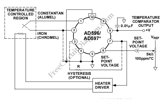
This is a setpoint controller circuit using The AD596/AD597. The thermocouple voltage is amplified, compared to an external setpoint voltage, and cold junction compensated. The device temperature can be monitored if the temperature to be controlled is within the operating range (–55°C to +125°C) of the device. Here is the schematic diagram of the circuit: Setpoint Voltage of AD597 is  […]

Read more

AD586/597 Temperature Transducer (Sensor)

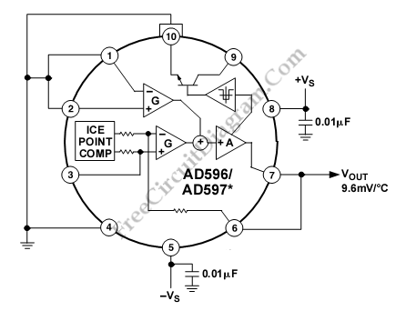
This is a stand alone temperature transducer/sensor circuit. This device uses The AD596/AD597, employing its internal junction compensation temperature sensor inside. This device can be used as temperature sensor by omitting the thermocouple and connecting the inputs (Pins 1 and 2) to common. Here is the schematic diagram of the circuit: The output will reflect the compensation voltage and the […]

Read more
1 7 8 9 10 11 22