Funk (Twang) Guitar Effect Box

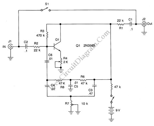
This is an audio effect circuit that give extra oscillation to your guitar, percussive, or semi percussive instruments, you can call it a funk box. This  guitar effect circuit is basically a damped oscillator that is set slightly below its critical oscillation point.  The oscillator part is constructed by feeding back the output signal through a bandpass circuit, with the […]

Read more

Capacitor ESR Meter

This is schematic diagram of capacitor ESR meter circuit. ESR is equivalent series resistance, and this parameter is used to express the resistance value of any electronic component that basically is not a resistor. ESR is present on many non-resistor component, such as capacitor, inductor, or semiconductor. The circuit shown in this schematic diagram is used to measure equivalent series […]

Read more

Direct High Voltage DC Regulator

This regulator circuit stabilize the output voltage at 200V directly (without a transformer). Although the output voltage is high, this circuit only suffer a tension of the voltage drop (Vinput-Voutput), which is suffered mainly by the transistors. The op-amp suffers even less tension, since it regulate the applied voltage at their pins around the level of transistor’s bias voltage level. […]

Read more

LM10 Battery Voltage Threshold Indicator

A battery threshold indicator circuit shown in the schematic diagram below has current regulation mechanism in driving the LED. A sufficient current should be satisfied at the minimum voltage but no excessive current when the voltage is at the highest level. Balance pin (5) is used as the reference  voltage for regulating the current. This pin generate 23 mV, which […]

Read more

Ring-Around LED Flasher

This schematic diagram shows a ring-around LED flasher circuit. This circuit will turn off two LEDs and turn on the other two until the timing cycle reverses. This circuit can be configured to flash four LEDs in sequential order  by pressing and holding S1 closed until only one of the LEDs is on then releasing it.  Here is the schematic […]

Read more

Variable Frequency And Duty Cycle Oscillator

A discrete oscillator circuit shown in the schematic diagram below is  a variable duty cycle and variable frequency oscillator, can be used to produce rectangular wave. This circuit has frequency range of 60 to 1,000 Hz. This circuit consist of one UJT (uni junction transistor) and two transistors that provide positive going output when emitter voltage exceeds NPN emitter voltage. […]

Read more

Scope’s Time Base Calibrator

A scope calibrator is a circuit that is used for calibrating the variable time base oscillator of general purpose scopes. This scope calibrator gives 100kHz reference, so if the scope is set to 10 cycles on 10 graticule divisions, then each division represents 10 microseconds or 100kHz. And each division will represent 1 Mhz or 1 microsecond if the scope […]

Read more
1 2 3