Inverting Amplifier with Op-Amp

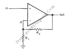
This is a Inverting amplifier circuit. This circuit is used to amplify the application that requires large(closed-loop) voltage gain since it has low input impedance. The output of this circuit is an amplified signal with different phase wit the input. This circuit uses a feedback. Here is the schematic diagram of the circuit:

The R1 is 10K and R2 is 100K, and the input voltage is +1V. A voltage divider is formed by R2 and R1 that hold the inverting input at +0.91V. When the input is unbalance, the output is forced to go negative until the output is at the needed, +10V. At that point, the both op-amp inputs are at the same voltage. When the input voltage is below the ground, the op-amp force the output voltage to rise. The voltage gain of this circuit is determined by following equation:
Vout/Vin = – R2/R1
And the input impedance is R1.