Voltage Controlled Variable Gain Video Amplifier
For you those are not familiar with analog circuits, it might seem difficult to find a practical application of analog video amplifier circuit. In today’s electronics, you might be wonder how such circuit can be useful in this digital domination era. You can see almost all of new devices provide digital interface for video, even a low cost Raspberry Pi single computer board has HDMI interface. But in some situation, there will be a need to interface old (legacy) into a new system, and that’s the reason why this very basic circuit is needed. For example, you have a VGA output only on your old device, but the whole new system accept only USB interface or other digital interface. Now you can find various micro controller with high speed ADC, and you would probably need this circuit for signal conditioner, making all RGB lines conversion uses the full range of the ADC.
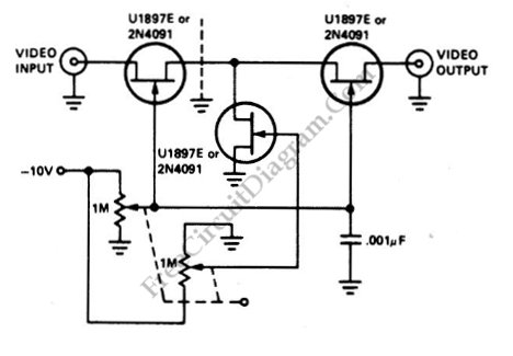
This is a video amplifier circuit featured with controllable variable gain. The control is done by adjusting the voltage of grid inputs of two FETs, which are configured as programmable voltage divider. This circuit can generate dynamic linear range attenuation up to 100 dB. This circuit still give a linear attenuation even at f=10.7MHz. You can see the control is done by a potentiometer, but you can replace with any voltage source ranging from zero to -10V, just make sure each of the two FETs is fed with different synchronized voltages. How to make this two synchronized voltages is described as follow: the first FET is fed with U1, which ranges from 0 to -10 V, and the second FET is controlled by U2, which is synchronized as (-10 – U1) V. This control voltages can be obtained from DAC (digital-to-analog converter) or a stereo potentiometer (as depicted in the diagram). You can see a grounded 0.001 uF capacitor to filter the control voltage from any glitch caused by dirty or bad potentiometer.