Archive for the ‘RF and Video’ Category
UHF Antenna Booster

UHF antenna booster can be used for better reception, especially when you’re far from TV station / relay transmitter. This UHF antenna booster works in 400-850 MHz range. Here is the circuit diagram of the UHF antenna booster: The circuit use only one transistor, but it gives you 10 to 15 dB amplification, enough for …[Read More]
Another Small Single Chip FM Transmitter

This FM transmitter circuit is small, similar to our previous single chip FM transmitter, but this FM transmitter is monophonic. You can see in the circuit’s schematic, the left and right signals is mixed before modulate the radio frequency. Here is the schematic diagram of the circuit: The core of this FM transmitter circuit …[Read More]

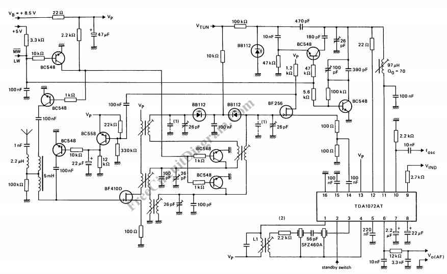
This antenna booster circuit can be used to amplify the weak signal received by the antenna. Antenna for AM/FM is usually not tuned for the optimal dimension of 1/4 wavelength, since we prefer small portable size. This untuned antenna has very low gain, so the antenna booster circuit here is very helpful in getting better …[Read More]
PLL Oscillator for Medium Wave Application

PLL oscillator is used to get very stable frequency woth very low distortion of sine wave output. The stability is equal to crystal-based oscillator, and the low distortion level of the sine wave output is equal to LC based oscillator. The method of PLL control in PLL oscillator is done by adjusting the frequency of …[Read More]
Pierce XTAL Oscillator Using JFET

This circuit is conventional “Pierce” type oscillator that uses a JFET. The circuit uses fundamental mode crystals. It has decent performance and reliability if we use a low noise JFET. The feedback is controlled by the C1 Capacitance from drain to ground. Adjusting the frequency can be done by adjusting a shunt capacitance C2 across …[Read More]
Crystal Oscillator Using Transistor, Capable of Overtone Operation

This circuit is a simple crystal oscillator that can be operated in overtone mode. Overtone mode permit the operation at higher frequency than specified by the crystal. The circuit uses a grounded base amplifier configuration, and place the crystal as a series resonator. The transistor Q1 is biased in the active region as an amplifier. …[Read More]
Another RF Field Strength Meter

This circuit is another radio frequency (rf) field strength meter, similar with our previous field strength meter circuit, but with lower supply voltage (only a single cell 1.5V battery). Here is the schematic diagram of this rf strength meter circuit: To use, turn on transmitter and meter; adjust C1 for peak reading. Turn off …
| 
