LM10 Battery Voltage Threshold Indicator
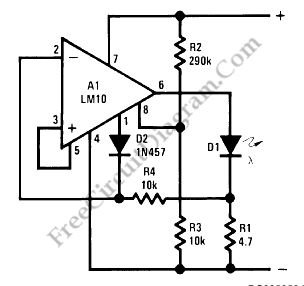
A battery threshold indicator circuit shown in the schematic diagram below has current regulation mechanism in driving the LED. A sufficient current should be satisfied at the minimum voltage but no excessive current when the voltage is at the highest level. Balance pin (5) is used as the reference  voltage for regulating the current. This pin generate 23 mV, which […]

Read more
Ring-Around LED Flasher

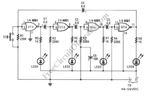
This schematic diagram shows a ring-around LED flasher circuit. This circuit will turn off two LEDs and turn on the other two until the timing cycle reverses. This circuit can be configured to flash four LEDs in sequential order  by pressing and holding S1 closed until only one of the LEDs is on then releasing it.  Here is the schematic […]

Read more

Color-Shifting LED Show

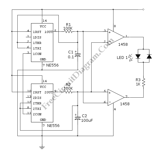
This circuit gives a changing-color LED display, where a LED will emit a dynamic shifting color, from red to green smoothly through yellow. The circuit uses NE556 dual timer, equal to two 555 IC but in only one package. The oscillators is set at different frequencies. The high frequency (upper part) is used to construct a PWM signal, and the […]

Read more

PWM RGB Controller

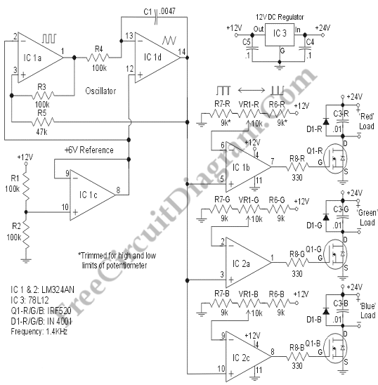
The design of a Pulse Width Modulated Red-Green-Blue controller will be explained here. This design is efficient because this design uses multiple strings of six LEDs with a 24V DC source. This design is sufficient for a sizeable light because a total current of 2 Amps will supply 600 LEDs per color. The circuit below makes use of a remarkable […]

Read more

LM3404 Constant Ripple LED Driver

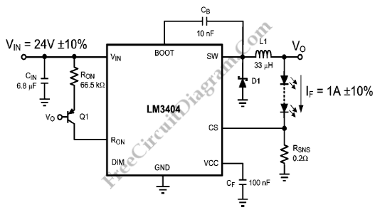
To take an input voltage of 24VDC ±10% and drive 1A through as many LEDs in series as the maximum output will allow, the circuit shown in the schematic diagram below uses the ONO-based constant ripple concept. The average current controls the luminous flux and dominant wavelength (or color temperature for white LEDs). Because the constant-ripple LED driver fixes the […]

Read more
1 2 3 4