5 A Constant Voltage-Constant Current Regulator
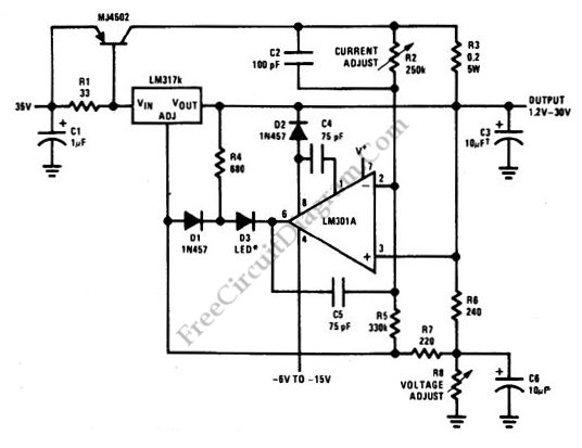
A constant voltage constant current (CVCS) regulator doesn’t mean a system with a constant load, since there will be no regulation in such case. What we call CVCS regulator is a regulator with two modes. The first mode is constant voltage, where the regulator trying to regulate the supply to a variable load at a constant voltage. In this mode […]
Read more