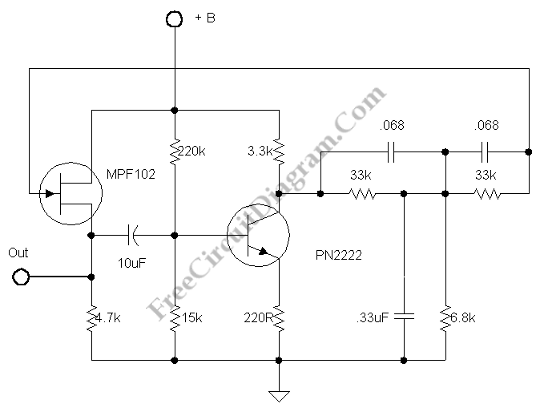
Complement Phase Inverter with Single Transistor

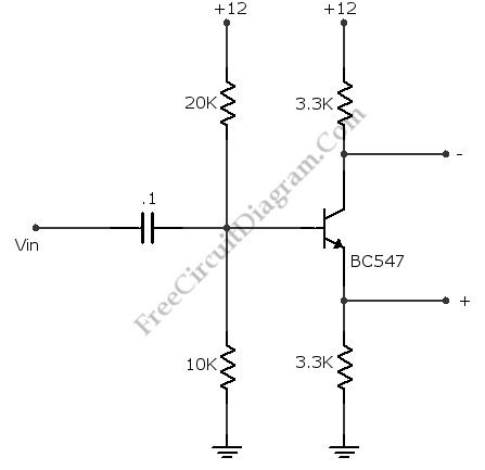
This is a complement phase inverter circuit. Sometimes this circuit called a paraphase amplifier circuit. This circuit has two output signals that is have sufficient “headroom” because this circuit is biased. The transistor will be saturated when the collector decreases, the emitter voltage increases and set the limit. Here is the circuit: This circuit can produces a peak to peak […]

Read more

Low Distortion Adjustable Audio frequency Oscillator

Low distortion circuit is very important if we want to measure distortion level of an audio equipment, but this is just one example of low distortion oscillator circuit application. Here is the schematic diagram: This oscillator is designed for audio application, with the adjustable frequency range of 30Hz to 20kHz, set by 470k pot. This potentiometer should be of stereo […]

Read more

Differentiator Operator with Op-Amp

Another application of OP-AMP is differentiator. Differentiator circuit produce an output if the input is changing. The output can positive or negative, depends on the change of the input: whether it’s decreasing or increasing.  This circuit is a bias stable. The current is produced by the rate of change of input voltage because the inverting input is grounded. Here is […]

Read more

Summing Amplifier with Op-Amp

One of inverting amplifier application is for summing several electric signals. The output of this circuit produce the sums of the input voltages.  We can use both positive or negative voltage for the inputs. The input resistors doesn’t have to be  same values. The input can be expanded to several digits. Since the point X is a virtual ground, the […]

Read more

Differential Amplifier with Op-Amp

The schematic diagram below shows a differential amplifier circuit. This circuit is used to get a common-mode rejection ratios. This circuit need a precise resistor matching to get common-mode rejection ratios because the current source uses matched resistor ratios. Here is the circuit: The gain of this circuit is determined by following equation: gain=R2/R1 The Vout is determined by following […]

Read more
1 4 5 6 7 8 20