Differential Current Sensing Inside H Bridge
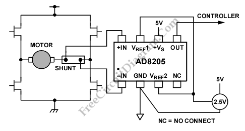
A differential current sensing that is inserted inside a H bridge circuit. is shown in the schematic diagram below. This circuit is one example of AD8205 application. The AD8205 measures current in both directions as the motor changes direction and H-bridge switches. This circuit has high accuracy in current measurement because AD8205 is placed in the middle of the H-bridge. […]

Read more
High Side Current Sensing for High Side Switching

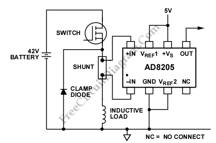
Sometimes, there are unexpected solenoid and excessive corrosion occurs on current sense circuit. Corrosive effects can be occurred because of the differential voltage between the ground and the load. To reduce that possibility, the shunt and the switch are placed on the high side. When switch is off, the battery is removed from the load, it will avoid damage from […]

Read more

High Side Current Sensing for Low Side Switching

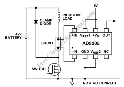
An AD8205 can be used to make a high-side current sense with a low side switch. Besides AD8205, an inductive load (solenoid) and a resistive shunt are added in this circuit. The resistive shunt is placed on high-side and the switch is placed on low-side, so that all current measurements, including the the re-circulation current, can be done because when […]

Read more

74HC11 Infra-Red Remote Control Tester

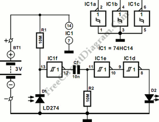
This is Infra-Red Remote Control Tester circuit. This circuit is used to test go/no-go of any remote control transmitting infra-red (IR) light. The supply of this circuit is 3V battery. This circuit has some advantages, such as fits in a compact enclosure, built from inexpensive parts and a handful of commonly available. As a quasi-analogue amplifier, this circuit uses Schmitt […]

Read more

OP90 4 mA to 20 mA Current Loop Transmitter

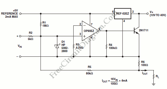
An output of 4 mA to 20 mA that is linearly proportional to the input voltage is provided by the current transmitter on figure below. Line rejection is 0.0005%/volt and linearity of the transmitter exceeds 0.004%. Here is the schematic diagram of this current loop circuit: The REF-02EZ provides biasing for the current transmitter. The output current is regulated by […]

Read more

Digitally Controlled Dual Polarity Amplifier

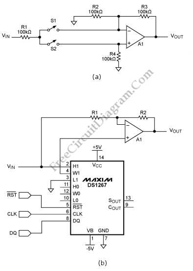
This schematic diagram below shows a Digitally Controlled Dual Polarity Amplifier circuit. The circuit (a) can give a means of amplifying a signal either in non inverting and inverting mode. When S2 is off and S1 is on, the noninverting input of the op amp is fed by the signal. The circuit behaves as a regular inverting amplifier, When switch  […]

Read more

Wheatston Bridge PWM Signal Conditioner

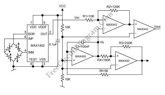
This is a schematic diagram of a Wheatston Bridge PWM Signal Conditioner circuit. This circuit uses the MAX1452 signal conditioner. A ratiometric compensated output for the Wheatstone Bridge is generated by the MAX1452. Then the output of the Wheatston bridge is converted to a PWM output. the PWM-output duty cycle changes accordingly, as the MAX1452 output changes with pressure. the […]

Read more
1 6 7 8 9 10 20