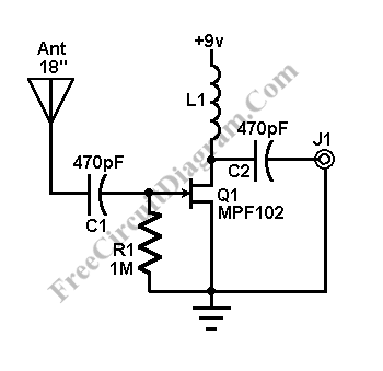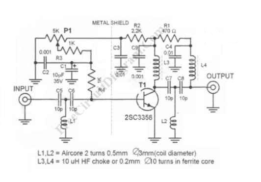
UHF Antenna Booster

UHF antenna booster can be used for better reception, especially when you’re far from TV station / relay transmitter. This UHF antenna booster works in 400-850 MHz range. Here is the circuit diagram of the UHF antenna booster: The circuit use only one transistor, but it gives you 10 to 15 dB amplification, enough for many situation. The most important […]

Read more
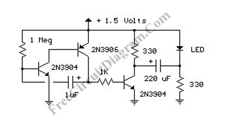
1.5V LED FLasher Using 3 Transistors

LED flasher circuit here will flash a LED using only 1.5 volts  supply voltage. Normally, to make any LED lamp works, you need more than 2 volts power supply. This because LED will work only when the supply voltage is higher than its forward bias voltage, around 2 volts  for red LED, and slightly lower for other color (but still […]

Read more

AM/FM Antenna Booster

This antenna booster circuit can be used to amplify the weak signal received by the antenna.  Antenna for AM/FM is usually not tuned for the optimal dimension of 1/4 wavelength, since we prefer small portable size. This untuned antenna has very low gain, so the antenna booster circuit here is very helpful in getting better signal reception. Here is the […]

Read more

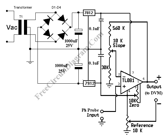
Simple pH Meter

pH Meter Circuit pH meter measures the voltage (the EMF, electromotive force) generated by the pH electrodes (the sensor) to show the hydrogen concentration in pH scale. Basically, a pH meter is nothing more than a pH probe/sensor with high impedance voltmeter that measures the generated voltage at the pH probe. To measure the pH with a standard digital voltmeter […]

Read more

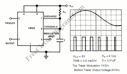
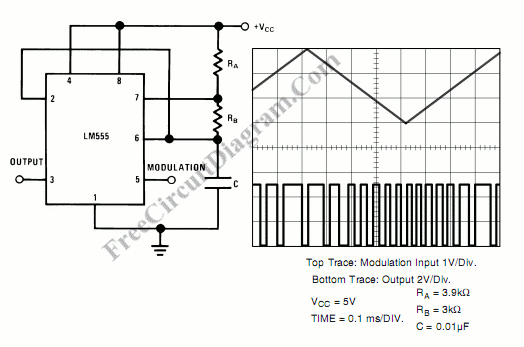
Pulse Position Modulator

Pulse position modulator can be easily built using 555 IC. Here is the schematic diagram of the circuit: Pulse position modulator modulate the on-period while keeping the fixed off-period. Pulse position modulation might substitute pulse-width modulation in some application. The main difference between pulse position modulation (PPM)  and pulse width modulation (PWM)  is that  unlike PWM, PPM doesn’t keep constant […]

Read more
1 15 16 17 18 19 40